
Exhaust emission control system
- Make
- Fiat
- Model
- Stilo Factory Service Manual
- Year
- 2001–2007
- Section
- Exhaust emission control system › Exhaust emission control system
Exhaust emission control system
Specifications
They are the 'planar' type and the first one is fitted downstream of the catalyzer and the second one in the downstream section. Their task is to inform the injection control unit of the progress of the combustion (stoichiometric ratio) and the operating condition of the catalyatic converter.
To obtain an optimum mixture, the quantity of air drawn in by the engine is the same as the theoretical quantity that would be needed to burn all the injected fuel.
In this case the Lambda factor (λ) the ratio between the quantity of air drawn in and the theoretical quantity of air (needed to burn all the injected fuel), is 1.
Thus:
- λ = 1 ideal mixture
- λ > 1 lean mixture
- λ < 1 rich mixture
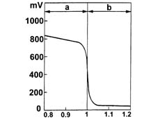
a, Rich mixture (too little air)
b, Lean mixture (too much air)
CONSTRUCTION features
The lambda probes are planar type. One is fitted immediately after the exhaust manifold but before the catalytic converter ('PRE), while the second is fitted immediately after the catalytic converter ('POST).
Both lambda probes supply the engine control unit with information on combustion progress; the pre catalytic converter probe analyses the stochiometric ratio while the post catalytic converter probe monitors catalytic converter operation and reports back to the engine control unit, which fine-tunes the stoichiometric ratio.
To obtain an optimum mixture, the quantity of air drawn in by the engine is the same as the theoretical quantity that would be needed to burn all the injected fuel.
The Lambda factor (λ) is the ratio between the quantity of air drawn in and the theoretical quantity of air and the ideal value is 1.
Thus:
- λ = 1 ideal mixture
- λ > 1 lean mixture
- λ < 1 rich mixture
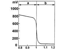
a, Rich mixture (lack of air)
b, Lean mixture (too much air)
Specifications
They are the 'planar' type and two are fitted downstream of the catalyzers and the third in the downstream section. Their task is to inform the injection control unit of the progress of the combustion (stoichiometric ratio) and the operating conditions of the catalytic converters.
To obtain an optimum mixture, the quantity of air drawn in by the engine is the same as the theoretical quantity that would be needed to burn all the injected fuel.
In this case the Lambda factor (λ) the ratio between the quantity of air drawn in and the theoretical quantity of air (needed to burn all the injected fuel), is 1.
Thus:
- λ = 1 ideal mixture
- λ > 1 lean mixture
- λ < 1 rich mixture
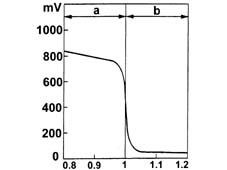
a, Rich mixture (too little air)
b, Lean mixture (too much air)
Lambda sensors
They are the 'planar' type and are fitted upstream and downstream of the catalyzer.
The upstream sensor carries out the check on the mixture strength known as the first loop.
The control unit controls and manages the injection so that the air/fuel ratio is always sufficiently close to the stoichiometric value to maximize the conversion efficiency of the catalyzer; in full power and high usage conditions, the mixture is enriched to guarantee maximum performance.
The downstream sensor is designed to diagnose the conversion efficiency of the catalyzer(s).
Thus:
- Lambda = 1 ideal mixture
- Lambda > 1 lean mixture
- Lambda < 1 rich mixture

a - Rich mixture (lack of air)
b - Weak mixture (too much air)
SPECIFCATIONS
The oxidizing catalyzer is a post-treatment device for oxidizing the CO, HC and particle matter, transforming them into carbon dioxide (CO2) and water vapour (H2O).
The catalytic converter consists of a ceramic, honeycomb structure monolith (1) with cells impregnated with platinum (2), which acts as a catalyst for the oxidation process.
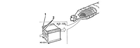
SPECIFCATIONS
The oxidizing catalyzer is a post-treatment device for oxidizing the CO, HC and particle matter, transforming them into carbon dioxide (CO2) and water vapour (H2O).
The catalytic converter consists of a ceramic, honeycomb structure monolith (1) with cells impregnated with platinum (2), which acts as a catalyst for the oxidation process.
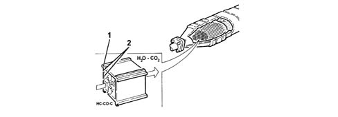
Specifications
The Lambda probe, placed in contact with the exhaust gases, generates an electrical signal whose voltage depends on the concentration of oxygen present in the gases.
This voltage undergoes a sudden variation when the composition of the mixture moves away from the value λ = 1.
The heating of the Lambda probe is managed by the fuel injection control unit in relation to the exhaust gas temperature.
This avoids thermal shocks on the ceramic casing due to the contact with condensed water, present in the exhaust gases when the engine is cold.
The measuring cell and heater are built into the 'planar' (stratified) ceramic element, with the advantage of obtaining quick heating of the cell, thus permitting a closed loop' check (λ = 1 within 10 seconds of engine start-up.
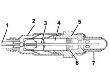
1, Connecting element
2, Protective sleeve
3, Planar sensor element
4, Ceramic tube casing
5, Sensor housing
6, Ceramic seal
7, Protective tube
COMPONENTS AND OPERATION
When brought into contact with exhaust gases, the Lambda probe generates an electrical signal whose voltage depends on the concentration of oxygen present in the gases.
Even though the lambda probes are the same, they work under different gas conditions and send the engine control unit a different signal; the signal from the pre catalytic converter probe is computed to correct the mixture concentration by the amount by which it deviates from λ = 1.
At the same time the post-sensor checks how much the catalyzer lowers the harmful exhaust gases and informs the control unit if these gases are more or less pollutant and the control unit ensures the optimum Lambda value = 1 using this parameter.
To prevent the ceramic case experiencing thermal shock due to condensation formation when the engine is cold, the engine control unit heats the pre and post catalytic converter lambda probes to bring their temperature ≈ to that of the exhaust gases.
The heater and measuring chamber are built into the 'planar' (laminated) ceramic element to promote fast chamber heating and thus allow a closed loop check within a short time of engine start-up.
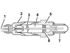
1, Connecting element
2, Protective sleeve
3, Planar sensor element
4, Ceramic tube casing
5, Sensor housing
6, Ceramic seal
7, Protective tube
Specifications
The Lambda probe, placed in contact with the exhaust gases, generates an electrical signal whose voltage depends on the concentration of oxygen present in the gases.
This voltage undergoes a sudden variation when the composition of the mixture moves away from the value λ = 1.
The heating of the Lambda probe is managed by the fuel injection control unit in relation to the exhaust gas temperature.
This avoids thermal shocks on the ceramic casing due to the contact with condensed water, present in the exhaust gases when the engine is cold.
The measuring cell and heater are built into the 'planar' (stratified) ceramic element, with the advantage of obtaining quick heating of the cell, thus permitting a closed loop' check (λ = 1 within 10 seconds of engine start-up.
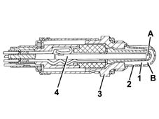
1, Connecting element
2, Protective sleeve
3, Planar sensor element
4, Ceramic tube casing
5, Sensor housing
6, Ceramic seal
7, Protective tube
Lambda sensors
The Lambda probe, placed in contact with the exhaust gases, generates an electrical signal whose voltage depends on the concentration of oxygen present in the gases. This voltage is characterized by a sudden change when the composition of the mixture moves away from Lambda = 1.
The heating of the Lambda sensor is managed by the fuel injection control unit in relation to the exhaust gas temperature.
This avoids thermal shocks on the ceramic casing due to the contact with condensed water, present in the exhaust gases when the engine is cold.
The measuring cell and heater are built into the 'planar' (stratified) ceramic element, with the advantage of obtaining quick heating of the cell, thus permitting a closed loop' check (Lambda = 1) within 10 seconds of engine start-up.
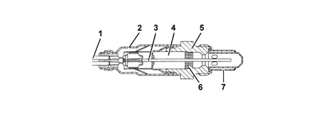
1 - Connecting cable
2 - Protective sleeve
3 - Planar sensor element
4 - Ceramic tube casing
5 - Sensor housing
6 - Ceramic seal
7 - Protective tube
OPERATION
The exhaust gases which pass through the cells heat the catalyzer, triggering the conversion of the pollutants into inert compounds.
The chemical reaction which causes the oxidation of the CO, HC, and particle matter takes place at temperatures of between 200 and 350°C.
In effect, at temperatures above 350°C the sulphur, contained in the diesel fuel, starts to oxidize, producing sulphur dioxide and sulphuric anhydride.
Specifications
The operation of the Lambda probe is based on the principle of an oxygen concentration cell with solid electrolyte.
The surfaces of the measuring cell are coated with microporous layers of noble material.
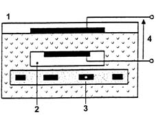
1, Exhaust gases
2, Passage of reference air
3, Heater
4, Lambda probe voltage
COMPONENTS AND OPERATION
Lambda sensor operation is based on the principle of an oxygen concentration chamber with solid electrolyte.
The surfaces of the measuring chamber are coated with microporous layers of noble material.
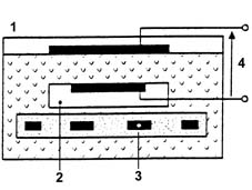
1, Exhaust gases
2, Passage of reference air
3, Heater
4, Reference voltage
Specifications
The operation of the Lambda probe is based on the principle of an oxygen concentration cell with solid electrolyte.
The surfaces of the measuring cell are coated with microporous layers of noble material.
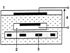
1, Exhaust gases
2, Passage of reference air
3, Heater
4, Lambda probe voltage
Lambda sensors
The operation of the Lambda probe is based on the principle of an oxygen concentration cell with solid electrolyte.
The surfaces of the measuring cell are coated with microporous layers of noble material.
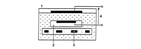
1 - Exhaust gas
2 - Passage of reference air
3 - Heater
4 - Lambda sensor voltage
Specifications
Electrical characteristics
- Heater supply: 12V
- Heater resistance: 0.5 - 1 kOhm.
COMPONENTS AND OPERATION
Electical properties:
- Heater power supply. 12V
- Heater coil 0.5 - 1 kO
Specifications
Electrical characteristics
- Heater supply: 12V
- Heater resistance: 0.5 - 1 kOhm.
Lambda sensors
Specifications
- Supply: 12V
- Internal resistance: 0.5 - 1 kOhm
The three-way catalytic converter simultaneously reduces the three polluting gases present in the exhaust gases:
- unburnt hydrocarbons (HC);
- carbon monoxide (CO);
- nitrogen oxides (NOx).
Two types of chemical reactions take place in the converter:
- oxidation of the CO and HC, converted into carbon dioxide (CO2) and water (H2O)
- reduction of the NOx converted into nitrogen (N2).
The converter consists of a monolith, a metal mesh support for damping impacts and vibrations and an outer stainless steel housing resistent to high temperatures and atmospheric agents.
The monolith consists of a honeycomb structure comprising a ceramic material coated with a very thin layer of catalytically active substances, platinum or rhodium. These accelerate the chemical decomposition of the harmful substances contained in the exhaust gases which, passing through the core cells at temperatures of over 300°-350°C, activate the catalyzers, thus starting the oxidoreduction reactions.
To optimze the efficiency and duration of the catalyzer, a perforated plate metal cone improves the diffusion of the exhaust gases in the cells of the ceramic core.
The noble metals contained in the catalytic converter, because of the high temperature, are chemically attacked if lead is present. For this reason the use of petrols containing lead should be avoided, otherwise the converter will be quickly and irreversibly damaged. Never use petrol containing lead, not even in an emergency or for a very short time.
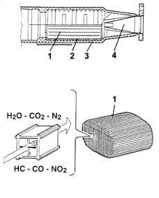
1, Ceramic monolith
2, Metal support
3, Outer casing
4, Perforated plate metal cone
CONSTRUCTION features
The emission control system includes devices designed to keep down the level of harmful emissions in the atmosphere.
- exhaust emissions
- vapour/gas emission from the crankcase
The three-way catalytic converter simultaneously reduces the three polluting gases present in the exhaust gases:
- unburnt hydrocarbons (HC);
- carbon monoxide (CO);
- nitrogen oxides (NOx).
Two types of chemical reactions take place in the converter:
- oxidation of the CO and HC, converted into carbon dioxide (CO2) and water (H2O)
- reduction of the NOx converted into nitrogen (N2).
The converter consists of a monolith, a metal mesh support for damping impacts and vibrations and an outer stainless steel housing resistent to high temperatures and atmospheric agents.
The monolith consists of a honeycomb structure comprising a ceramic material coated with a very thin layer of catalytically active substances, platinum or rhodium. These accelerate the chemical decomposition of the harmful substances contained in the exhaust gases which, passing through the core cells at temperatures of over 300°-350°C, activate the catalyzers, thus starting the oxidoreduction reactions.
To optimze the efficiency and duration of the catalyzer, a perforated plate metal cone improves the diffusion of the exhaust gases in the cells of the ceramic core.
The noble metals contained in the catalytic converter, because of the high temperature, are chemically attacked if lead is present. For this reason the use of petrols containing lead should be avoided, otherwise the converter will be quickly and irreversibly damaged. Never use petrol containing lead, not even in an emergency or for a very short time.
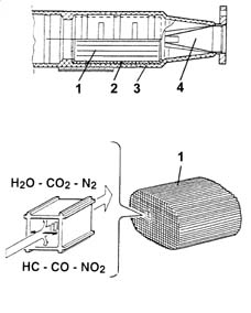
1, Ceramic monolith
2, Metal support
3, Outer casing
4, Perforated plate metal cone
Catalytic converter
The three-way catalytic converter simultaneously reduces the three polluting gases present in the exhaust gases:
- unburnt hydrocarbons (HC);
- carbon monoxide (CO);
- nitrogen oxides (NOx).
Two types of chemical reactions take place in the converter:
- oxidation of the CO and HC, converted into carbon dioxide (CO2) and water (H2O)
- reduction of the NOx converted into nitrogen (N2).
The converter consists of a monolith, a metal mesh support for damping impacts and vibrations and an outer stainless steel housing resistent to high temperatures and atmospheric agents. The monolith consists of a honeycomb structure comprising a ceramic material coated with a very thin layer of catalytically active substances, platinum or rodium. These accelerate the chemical decomposition of the harmful substances contained in the exhaust gases which, passing through the core cells at temperatures of over 300-350 degrees C, activate the catalyzers, thus starting the oxidoreduction reactions.
The noble metals contained in the catalytic converter, because of the high temperature, are chemically attacked if lead is present. For this reason the use of petrols containing lead should be avoided, otherwise the converter will be quickly and irreversibly damaged. Never use petrol containing lead, not even in an emergency or for a very short time.
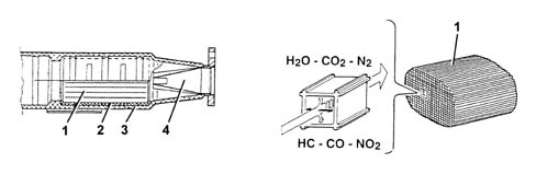
1 - Ceramic monolith
2 - Metal support
3 - Outer casing
4 - Perforated plate metal cone
CONSTRUCTION features and composition
The catalytic converter is used to reduce emissions of the three main pollutants:
- HYDROCARBONS = HC
- NITROGEN OXIDES = NoX
- CARBON MONOXIDE = CO
Briefly, the catalytic converter consists of a metal mount coated in a substrate. This in turn contains chemically active material that triggers and facilitates two chemical reactions, i.e. oxidation to reduce CO and HC and reduction to reduce NoX.
The active elements are generally made out of noble materials. RHODIUM and PALLADIUM are used for the reduction reactions, while PLATINUM is used for oxidation.
The substrate also contains other chemical compounts that serve the fundamental purpose of storing and releasing oxygen required to carry out chemical reactions.
This feature of catalytic converters is known as OXYGEN STORAGE.
OPERATING
The substrate of the new oxygen store catalytic converter contains chemical compounds that store and release the oxygen required for chemical reactions.
Oxygen storage takes place when the mixture is lean. The oxygen required for oxidation is released when the mixture is rich.
This function is typical of oxygen store catalytic converters.
An old or deteriorated catalyzer is less efficient at carrying out the chemical reactions with a consequent increase in pollutant emissions; the new OXYGEN STORAGE catalyzer works efficiently and the post-sensor catalyzer supplies an almost constant output voltage since the catalyzer uses all the oxygen for its chemical reactions.
As the catalytic converter ages, the OXYGEN STORAGE effect drops gradually and the post catalytic converter probe uses less and less oxygen. Output voltage continues to increase but the frequency is the same as that of the post catalytic converter probe.
The noble metals contained in the catalytic converter, because of the high temperature, are chemically attacked if lead is present. For this reason the use of petrols containing lead should be avoided, otherwise the converter will be quickly and irreversibly damaged. Never use petrol containing lead, not even in an emergency or for a very short time.
Parts & tools for this job For 2001 Fiat Stilo
- PARTExhaust gasketSearch: Fiat Stilo 2001 exhaust gasket
- TOOLPenetrating oilSearch: penetrating oil
- TOOLOBD2 scannerSearch: OBD2 scanner
Links open Amazon search results in a new tab. As an Amazon Associate I earn from qualifying purchases.