
Engine management system - MEMS (Alternator): Description and operation
- Make
- Land Rover
- Model
- Freelander System Description and Operation (UK)
- Section
- Description and operation › Alternator
If evaporator temperature falls low enough for ice to form on the evaporator fins, the ECM will disengage the compressor electro-mechanical clutch until evaporator temperature rises sufficiently. AIR CONDITIONING, DESCRIPTION AND OPERATION, Description.
Alternator
The alternator is located on a bracket which is attached to the cylinder block on the front RH side of the engine. The alternator is driven by a Polyvee belt from the crankshaft pulley. The alternator converts mechanical energy into electrical energy to power the electrical systems and maintain the battery charge.
The alternator outputs a signal to pin 35 of ECM connector C0914 which represents the electrical load on the vehicle systems and the mechanical load exerted on the engine by the alternator. The signal output from the alternator is a variable PWM signal which is proportional to the load applied to the engine.
The ECM uses the load signal to provide idle speed compensation and to reduce engine speed fluctuations. If the load signal fails, the ECM uses a default value and stores a fault code which can be retrieved using TestBook.
Ignition Switch Signal
A hardwired digital input to pin 61 of ECM connector C0913 provides an ignition on signal. When the ECM has been idle for a period of time, it goes into 'sleep' (power saving) mode.
When the ECM receives an ignition on signal from the ignition switch, the ECM 'wakes up' and energises the main relay.
Main Relay
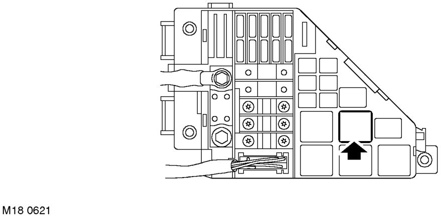
The main relay is located in the engine compartment fusebox which is located on the LH side of the engine compartment.
The main relay is normally open when the ignition is off. When the ignition is switched on to position II, the ECM provides an earth path for the relay coil which energises, closing the contacts.
A permanent battery supply is provided direct to the relay contacts. The main relay supplies battery voltage to the following components: l ECM connector C0914 pin 19 l Pre and post HO2S. l CMP sensor. l Purge valve. l Fuel injectors. l Ignition coils. l A/C relay coil. l Fuel pump relay coil.
If the main relay fails, power will not be supplied to the above components and the engine will not start. The ECM will store fault codes which can be retrieved using TestBook.
Parts & tools for this job For Land Rover Freelander
- TOOLBattery testerSearch: car battery tester
- TOOLDigital multimeterSearch: automotive digital multimeter
- TOOLBattery terminal cleanerSearch: battery terminal cleaner
Links open Amazon search results in a new tab. As an Amazon Associate I earn from qualifying purchases.