
Heated Oxygen Sensors (HO2S)
- Make
- Land Rover
- Model
- Freelander System Description and Operation (UK)
- Section
- Description and operation › Heated Oxygen Sensors (HO2S)
Two harness connectors, C0913 and C0914 are used to connect the ECM to the main harness. The ECM is connected to earth using three wires. Pins 59, 66 and 73 of ECM connector C0913 are connected to a body earth at connector C1964, C1947 and C1413 respectively. With the ignition off, the ECM is supplied with permanent battery voltage to power the memory. The voltage is supplied from the battery positive terminal via the engine compartment fusebox fusible link 1 and fuse 5 to pin 80 of ECM connector C0913.
When the ignition switch is in position II (ignition on), the ECM receives battery voltage, via the engine compartment fusebox fusible link 3 and the passenger compartment fusebox fuse 6, to pin 61 of ECM connector C0913. The ECM energises the main relay by completing the earth path for the relay coil which is connected to the ECM at pin 54 of connector C0913. The main relay provides battery voltage to various peripheral components and also to the ECM at pin 19 of connector C0914.
When the ignition switch is turned to position II, the ECM primes the fuel system by running the fuel pump for approximately two seconds. This is achieved by completing the earth path for the fuel pump relay coil. The fuel pump relay coil is connected to battery voltage from the main relay, the earth being supplied by the ECM at pin 68 of connector C0913. The ECM references the sensors and the IACV stepper motor prior to start-up.
Security code information is exchanged between the ECM and the immobilisation ECU via a wire connected from pin 72 of connector C0913 on the ECM.
When the ignition switch is turned to position III (crank), the ECM communicates with the immobilisation ECU. If it receives authority to start, the ECM begins ignition and fuelling when CKP and CMP sensor signals are detected. The ECM will run the fuel pump continuously when CKP sensor signals are received (crank turning).
When the ignition switch is turned to position 0 (off), the ECM switches off ignition and fuelling to stop the engine. The ECM continues to hold the main relay in the on position until it has completed the power down functions. Power down functions include engine cooling and referencing the IACV stepper motor and includes memorising data required for the next start up. When the power down process is completed, the ECM switches off the main relay and enters a low power mode. During low power mode the ECM will consume less than 1mA.
If the ECM suffers an internal failure, such as a break down of the processor or driver circuits, there are no back up systems or limp home capability. If a sensor circuit fails to supply an input, this will result in a substitute or default value being adopted where possible. This enables the vehicle to function, but with reduced performance.
Heated Oxygen Sensors (HO2S)
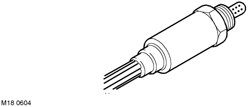
Two HO2S are used on the MEMS 3 system to comply with the requirements of ECD 3. A pre-catalyst HO2S is located in the exhaust manifold, upstream of the starter catalyst and a post catalyst HO2S is located in the exhaust system, downstream of the main catalyst. The sensors provide feedback signals to the ECM which enable it to control the Air/ Fuel Ratio (AFR). The principal purpose of the sensors is to enable tight control of AFR around the 14.7:1 AFR (by weight) which produces the best composition of exhaust gas for peak catalytic converter efficiency.
The upstream (pre-catalyst) sensor is the main sensor used for closed loop fuelling. The downstream (post-catalyst) sensor is used to monitor the performance of the main catalyst and to trim the fuelling provided by the pre-catalyst sensor.
If an HO2S fails, the ECM adopts an open loop fuelling strategy to minimise emissions, stores fault codes which can be retrieved using TestBook and, on vehicles manufactured after the EDC3 compliance date, illuminates the Malfunction Indicator Lamp (MIL) in the instrument pack.
Parts & tools for this job For Land Rover Freelander
- PARTOxygen sensorSearch: Land Rover Freelander oxygen sensor
- TOOLOxygen sensor socketSearch: oxygen sensor socket
- TOOLOBD2 scannerSearch: OBD2 scanner
Links open Amazon search results in a new tab. As an Amazon Associate I earn from qualifying purchases.