
Ground distribution – circuit diagram
- Make
- Land Rover
- Model
- Range Rover Classic Electrical Troubleshooting Manual
- Year
- 1995
- Section
- Circuit diagram › Ground distribution – circuit diagram
Ground distributionGround distribution – circuit diagram
GROUND DISTRIBUTION – CIRCUIT DIAGRAM
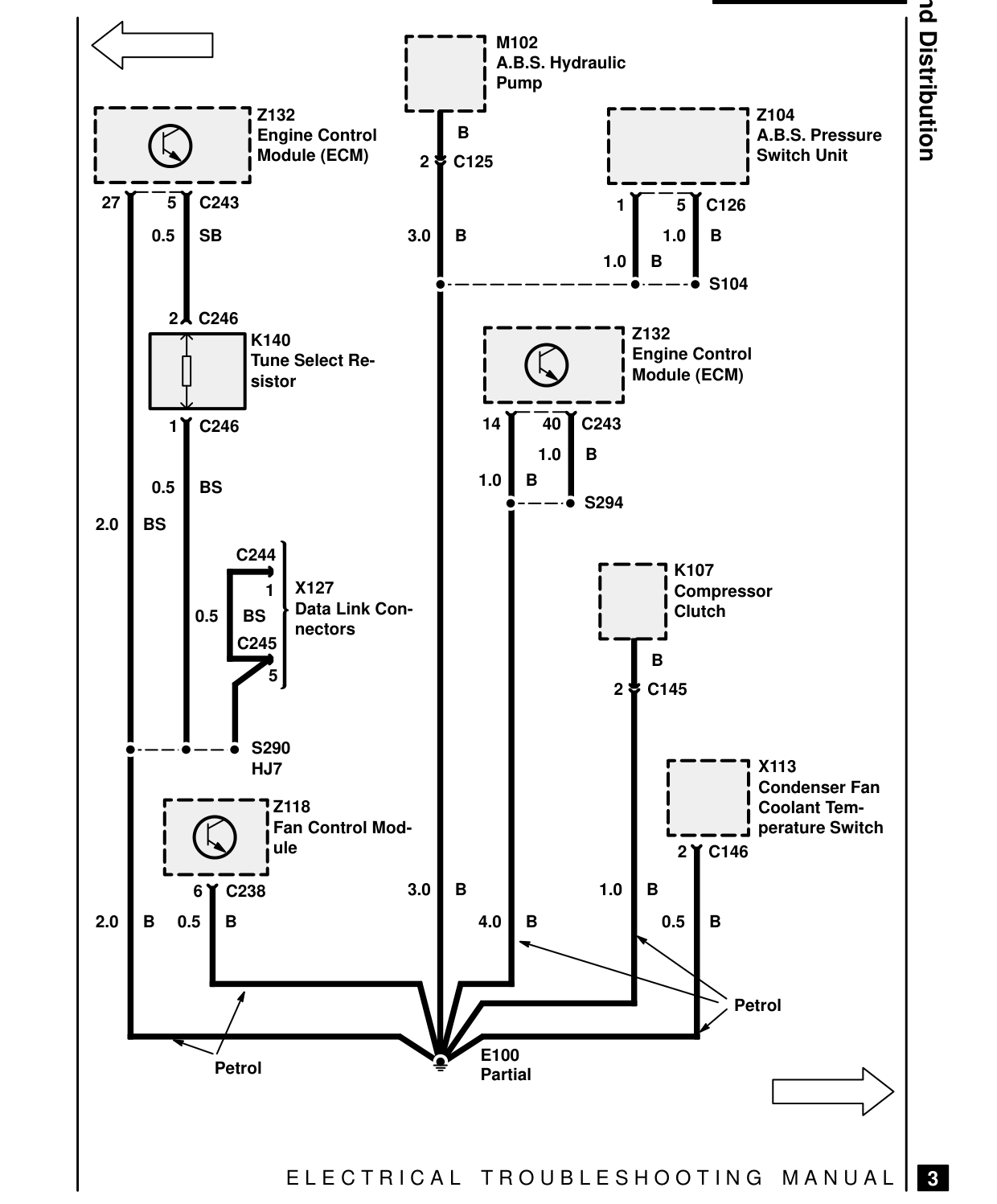
Z132 B Engine Control Module (ECM) 2 C125
C243 27 5
0.5 SB 3.0 B
2 C246 K140 Tune Select Re- sistor
1 C246
0.5 BS
2.0 BS C244 X127 1 Data Link Con- 0.5 BS nectors C245 5
S290 HJ7
Z118 Fan Control Mod- ule
3.0 B 6 C238 2.0 B 0.5 B
Petrol
E L E C T R I C A L
Ground Distribution M102 A.B.S. Hydraulic Pump Z104 A.B.S. Pressure Switch Unit
5 1 C126 1.0 B 1.0 B S104
Z132 Engine Control Module (ECM)
40 14 C243 1.0 B 1.0 B S294
K107 Compressor Clutch
B 2 C145
X113 Condenser Fan Coolant Tem- perature Switch 2 C146
1.0 B 4.0 B 0.5 B
Petrol
E100 Partial
T R O U B L E S H O O T I N G M A N U A L
3
Parts & tools for this job For 1995 Land Rover Range Rover
- TOOLDigital multimeterSearch: automotive digital multimeter
- PARTAssorted fuse kitSearch: car fuse assortment kit
- TOOLWire crimper and connector kitSearch: wire crimper connector kit
Links open Amazon search results in a new tab. As an Amazon Associate I earn from qualifying purchases.