
All engines (page 4 of 4)
- Make
- Rover
- Model
- 400 Workshop Manual
- Year
- 1995–2000
- Section
- Repairs
Engine - K SeriesAll engines · page 4 of 4
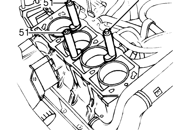
- Fit cylinder liner clamps 18G 1736 to cylinder block and secure with cylinder head bolts.
CAUTION: Do not rotate crankshaft with cylinder head removed.
Refit
- Remove bolts securing cylinder liner clamps to cylinder block and remove clamps.
- Clean joint surfaces of cylinder head and cylinder block. Clean oil and coolant passages. Clean mating face of exhaust manifold and exhaust front pipe. If necessary, de-carbonise piston crowns and cylinder head.
- Clean cylinder head bolts with a wire brush. Inspect cylinder head bolts for signs of damage.
- Wash cylinder head bolts and wipe dry. Apply a light film of oil to bolt threads and underside of bolt heads.
- Clean location dowels and fit to cylinder block.
- Fit new cylinder head gasket, dry, to cylinder block.
- Using assistance, fit cylinder head onto cylinder block carefully locating on dowels.
CAUTION: Take care not to damage heated oxygen sensor when refitting cylinder head.
- Carefully enter cylinder head bolts, DO NOT DROP. Screw bolts into place by hand.
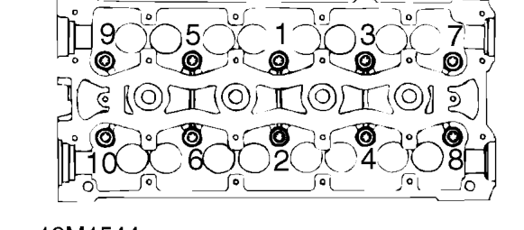
- Working in the sequence shown, progressively tighten the cylinder head bolts using the following procedure. i.All bolts to 20 Nm. Use a felt tip pen and mark position of radial mark on each bolt head. ii.Turn all bolts through 180°. iii.Turn all bolts through another 180°and align radial mark.
CAUTION: If bolt is overtightened, back off 90°then realign radial marks.
- Fit camshaft cover. See this section.
- Connect h.t. leads to distributor cap.
- Connect expansion tank hose to inlet manifold and tighten clip.
- Connect vacuum hose to inlet manifold.
- Secure throttle cable to 2 clips on inlet manifold, ensure throttle cable is correctly routed.
- Connect brake servo vacuum hose to inlet manifold.
- Connect throttle cable to throttle cam.
- Locate throttle cable adjusting nut in abutment bracket.
- Connect purge hose to throttle housing and secure with clip.
- Remove plugs from fuel system hoses and components.
- Connect hose to fuel return pipe and secure with clip.
- Clean union of fuel filter and fuel outlet pipe.
- Connect fuel outlet pipe to fuel filter and tighten union to 30 Nm.
- Connect multiplug to IACV.
- Connect HO2S multiplug to engine harness and secure to clip on bracket.
Parts & tools for this job For 1995 Rover 400
- PARTEngine gasket setSearch: Rover 400 1995 engine gasket set
- TOOLTorque wrenchSearch: 3/8 inch torque wrench
- TOOLFeeler gauge setSearch: feeler gauge set
Links open Amazon search results in a new tab. As an Amazon Associate I earn from qualifying purchases.