
Power steering rack - ’l’ and ’t’ series (page 3 of 3)
- Make
- Rover
- Model
- 400 Workshop Manual
- Year
- 1995–2000
- Section
- Repairs
SteeringPower steering rack - ’l’ and ’t’ series · page 3 of 3
Refit
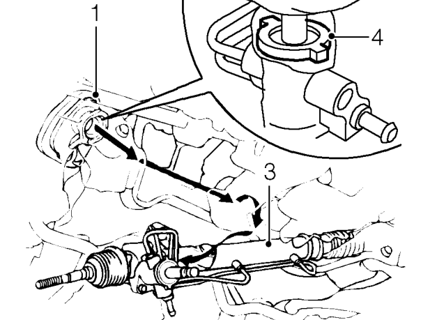
- Ensure body aperture seal is seated correctly on flange.
- Extend rack fully to passenger’s side.
- Fit rack from drivers side and feed rack in far enough for driver’s side tie-rod to clear subframe.
- Centralise rack and fit pinion shaft seal.
CAUTION: Ensure slot in seal is located to tab on pinion housing.
- Raise rack and locate pinion through body aperture.
CAUTION: Take care not to dislodge aperture seal.
- Align rack and fit bolts, driver’s side, DO NOT TIGHTEN.
- Fit clamp rubber and clamp, fit bolts and tighten to 38 Nm.
- Tighten bolts securing driver’s side to 58 Nm.
- Connect selector rod to shaft and align holes.
- Fit NEW roll pin securing selector rod to shaft and fit roll pin retaining clip.
- Fit washers to gear change steady bar and connect to gearbox.
- Fit exhaust front pipe. See MANIFOLD & EXHAUST SYSTEMS, Repairs.
- Align engine steady bar and fit through bolt. Tighten both bolts to 100 Nm.
- Position each locknut on tie-rods with equal threads exposed, as noted during removal.
- Centralise steering rack and screw both tie-rod ends on to tie-rods up to locknuts, ball pin facing downwards.
- Connect tie-rod ends, fit nuts and tighten to 39 Nm. Align nuts to next split pin hole and fit NEW split pins.
- Fit road wheel(s) and tighten nuts to correct torque. See INFORMATION, Torque wrench settings.
- Remove stand(s) and lower vehicle.
- Clean feed and return pipe and unions.
- Connect feed pipe to steering rack and tighten union to 37 Nm.
- Connect return hose to rack and secure with clip.
- Connect column universal joint. Fit bolts, ensuring lower bolt is located in groove on pinion shaft, tighten bolts to 28 Nm.
- Fit universal joint cover, fit clips and retaining studs.
- Position footwell carpet.
- Check and adjust front wheel alignment. See Adjustments.
- Bleed powering system. See Adjustments.
Parts & tools for this job For 1995 Rover 400
- TOOLTie rod end toolSearch: tie rod end puller
- TOOLBall joint separatorSearch: ball joint separator
- FLUIDPower steering fluidSearch: Rover power steering fluid
Links open Amazon search results in a new tab. As an Amazon Associate I earn from qualifying purchases.