
Evap two way valve testing
- Make
- Rover
- Model
- 600 Rover 600 Repair Manual - Volumes 1 and 2 - 2nd Edition
- Section
- Repairs › Evap two way valve testing
Engine management system – PGM-FiEvap two way valve testing
EVAP TWO WAY VALVE TESTING
- Remove the fuel filler cap.
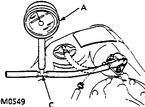
A Vacuum/Pressure Gauge
B Vacuum Pump/Gauge
C T piece
- Remove the vapour line from the fuel tank and connect to T piece from vacuum gauge and vacuum pump as shown.
- Apply vacuum slowly and continuously while watching the gauge.
Vacuum should stabilise momentarily at 5 to 15 mmHg.
- If vacuum stabilises (i.e. valve opens) below 5 mmHg or above 15 mmHg, install a new valve and retest.
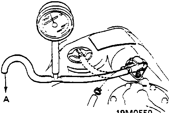
A Pressure side
- Move vacuum pump hose from vacuum to pressure fitting, and move vacuum gauge hose from vacuum to pressure side as shown.
- Slowly pressurise the vapour line while watching the gauge.
Pressure should stabilise at 10 to 35 mmHg.
- If pressure momentarily stabilises (i.e. valve opens) between 10 to 35 mmHg, the valve is OK.
- If pressure stabilises (i.e. valve opens) below 10 mmHg or above 35 mmHg, install a new valve and retest.
CATALYST OVERHEAT SENSOR
Remove
- Raise vehicle on a ramp.
- Remove 4 securing screws and remove lower heat shield from catalyst.
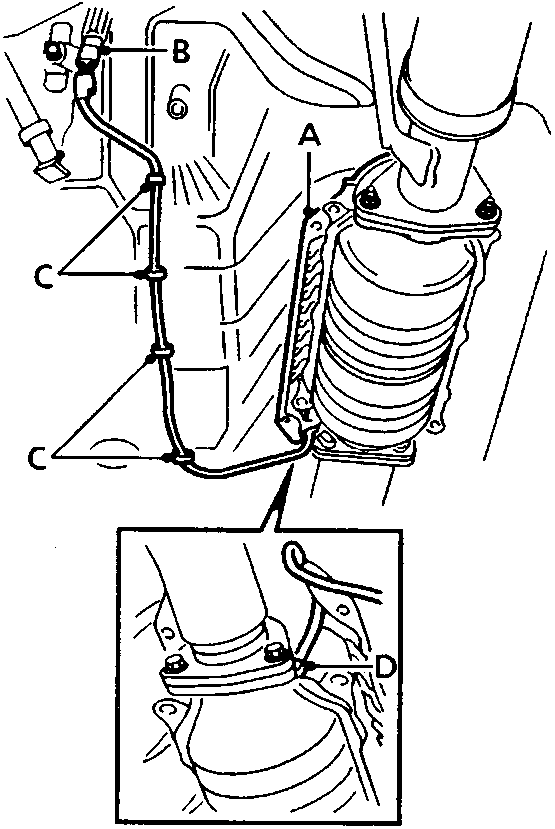
A Upper height shield
B Sensor connector – 2P
C Harness clips
D Catalyst overheat sensor
- Raise upper heat shield, move rearwards and retain against floor panel.
- Remove bolt securing connector clip and disconnect sensor 2P connector.
- Release harness from 4 clips.
- Unscrew union and withdraw overheat sensor from catalyst.
Refit
- Apply anti-seize compound to overheat sensor thread and tighten to 45 Nm.
- Fit heat shields and tighten screws to 10 Nm.
- Connect harness and clip to floor.
Parts & tools for this job For Rover 600
- PARTEngine gasket setSearch: Rover 600 engine gasket set
- TOOLTorque wrenchSearch: 3/8 inch torque wrench
- TOOLFeeler gauge setSearch: feeler gauge set
Links open Amazon search results in a new tab. As an Amazon Associate I earn from qualifying purchases.