
Replacement
- Make
- Rover
- Model
- 600 Rover 600 Repair Manual - Volumes 1 and 2 - 2nd Edition
- Section
- Repairs › Replacement
Engine management system – PGM-FiReplacement · page 1 of 2
Replacement
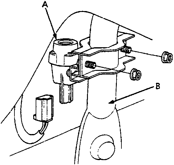
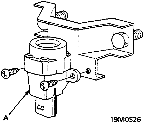
- A Inertia switch
- B Steering hanger pipe
PGM – Fi MAIN RELAY
Testing
Note: If the car starts and continues to run, the PGM – Fi main relay is OK.
- Remove the PGM – Fi main relay.
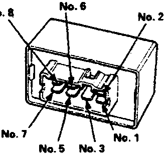
- A To IGN 1
- B To BAT +
- C To ECM (A25, B1)
- D To fuel pump
- E To ECM (A7, 8)
- F To ST switch
- G To EARTH
- Attach the battery positive terminal to the No. 6 terminal and the battery negative terminal to the No. 8 terminal of the PGM – Fi main relay. Then check for continuity between the No. 5 terminal and No. 7 terminal of the PGM – Fi main relay.
- If there is no continuity, replace the PGM – Fi main relay and retest.
- If there is continuity carry on following the procedure.
- Attach the battery positive terminal to the No. 5 terminal and the battery negative terminal to the No. 2 terminal of the PGM – Fi main relay. Check that there is continuity between the No. 1 terminal and No. 3 terminal of the PGM – Fi main relay.
- If there is no continuity, replace the PGM – Fi main relay and retest.
Parts & tools for this job For Rover 600
- PARTEngine gasket setSearch: Rover 600 engine gasket set
- TOOLTorque wrenchSearch: 3/8 inch torque wrench
- TOOLFeeler gauge setSearch: feeler gauge set
Links open Amazon search results in a new tab. As an Amazon Associate I earn from qualifying purchases.