
Inspection
- Make
- Rover
- Model
- 600 Rover 600 Repair Manual - Volumes 1 and 2 - 2nd Edition
- Section
- Repairs › Inspection
Engine management system – PGM-FiInspection
Inspection
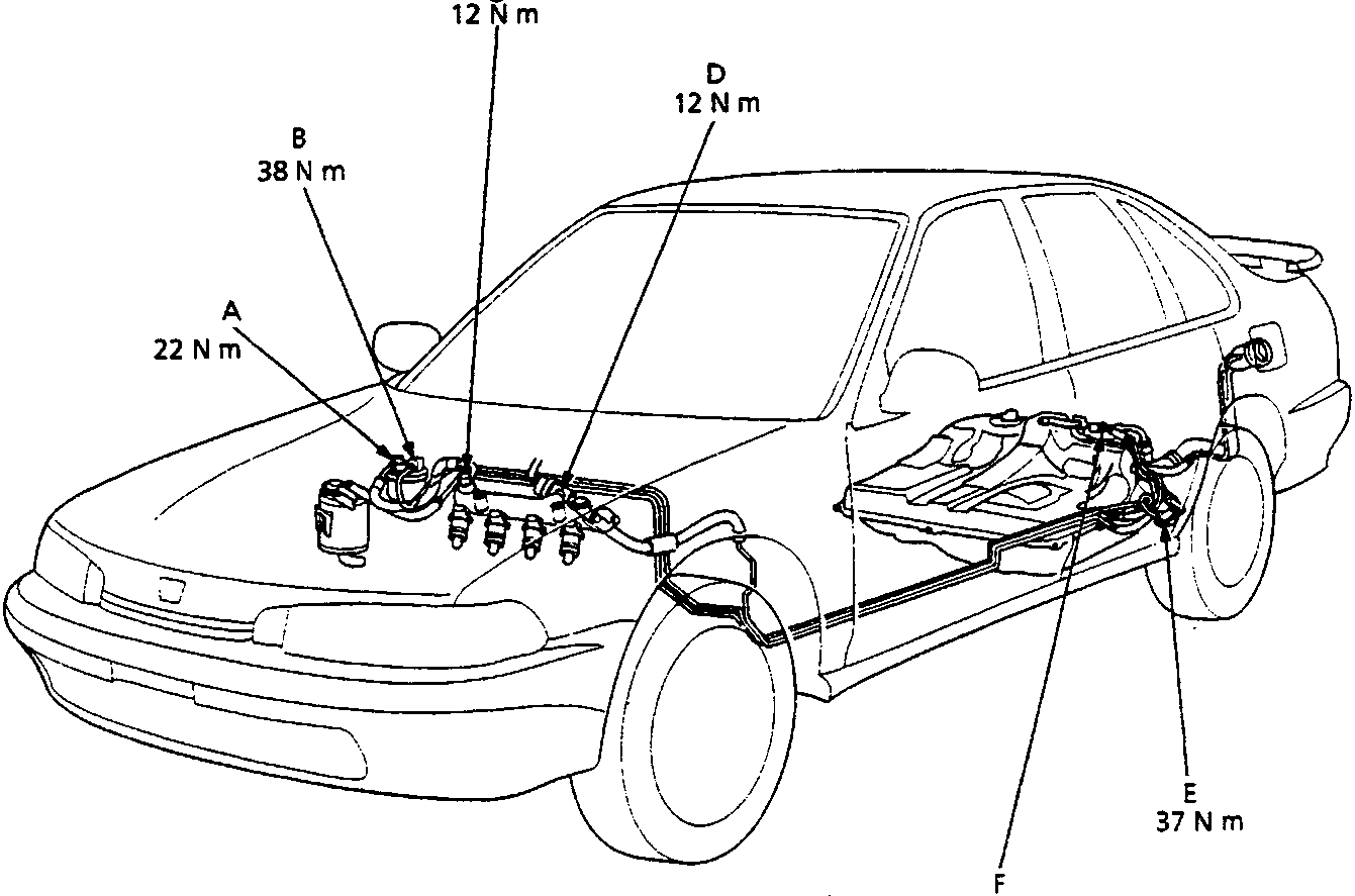
- A Banjo bolt
- B Fuel filter bolt
- C Service bolt
- D Fuel pressure regulator
- E Fuel feed pipe join
- F Fuel pump unit
- Inspect the fuel hoses for damage, leaks, interference or twisting.
- Check the fuel lines for damage, tipping, rusting or leakage. Also check for bent fuel lines.
- Check for leaks at hose and line joints or connections, and retighten if necessary.
CAUTION:
- When disconnecting the hoses, slide back the clamps, then twist hoses as you pull, to avoid damaging them.
- Clean the flared joint of high pressure hoses thoroughly before reconnecting them.
Parts & tools for this job For Rover 600
- PARTEngine gasket setSearch: Rover 600 engine gasket set
- TOOLTorque wrenchSearch: 3/8 inch torque wrench
- TOOLFeeler gauge setSearch: feeler gauge set
Links open Amazon search results in a new tab. As an Amazon Associate I earn from qualifying purchases.