
Refit
- Make
- Rover
- Model
- 600 Rover 600 Repair Manual - Volumes 1 and 2 - 2nd Edition
- Section
- Repairs › Refit
Refit
WARNING: Do not smoke while working on fuel system. Keep open flame away from your work area.
- Secure the new fuel filter in position with the clamp and the bolt. Tighten the bolt to 10 Nm.
- Using new sealing washers fit the fuel pipe to the fuel filter. Fit and tighten the banjo bolt to 22 Nm.
CAUTION: Clean the flared joint of high pressure pipes thoroughly before reconnecting them.
- Fit the fuel pipe and secure with the nut. Tighten the nut to 38 Nm.
FUEL PUMP
Testing
WARNING: Do not smoke during the test. Keep open flame away from your work area.
If you suspect a problem with the fuel pump, check that the fuel pump actually runs; when it is ON, you will hear some noise if you position your ear by the fuel filler neck with the fuel filler cap removed. The fuel pump should run for two seconds, when ignition switch is first turned ON. If there is no noise, check as follows:
Note: (KE) After an impact, the inertia switch must be reset by pressing the button before the testing.
- Remove the rear seat.
- Disconnect the 3P connector in luggage compartment area.
CAUTION: Be sure to turn the ignition switch OFF before disconnecting the wires.
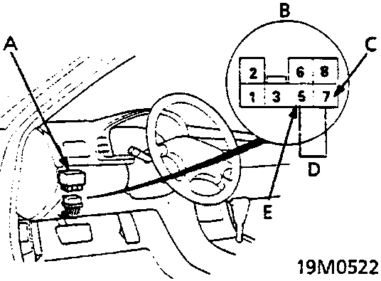
- A PGM – Fi main relay
- B View from terminal side
- C YEL (7)
- D Jumper wire
- E BLK/YEL (5) (KE: BLK/RED (5))
- Disconnect the PGM – Fi main relay connector and connect the BLK/YEL (5) (KE: BLK/RED (5)) wire and YEL (7) wire with a jumper wire.
Parts & tools for this job For Rover 600
- PARTEngine gasket setSearch: Rover 600 engine gasket set
- TOOLTorque wrenchSearch: 3/8 inch torque wrench
- TOOLFeeler gauge setSearch: feeler gauge set
Links open Amazon search results in a new tab. As an Amazon Associate I earn from qualifying purchases.