
Inspection/Adjustment
- Make
- Rover
- Model
- 600 Rover 600 Repair Manual - Volumes 1 and 2 - 2nd Edition
- Section
- Repairs › Inspection/Adjustment
Engine management system – PGM-FiInspection/Adjustment
Inspection/Adjustment
- Warm up the engine to normal operating temperature (the radiator fan comes ON).
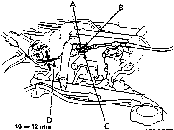
A Locknut
B Adjusting nut
C Cable bracket
D Deflection
- Check that the throttle cable operates smoothly with no binding or sticking. Repair as necessary.
- Check cable free play at the throttle linkage. Cable deflection should be 10 ÷ 12 mm.
- If deflection is not within specs, loosen the locknut, turn the adjusting nut until the deflection is as specified, then retighten the locknut.
- With the cable properly adjusted, check the throttle valve to be sure it opens fully when you push the accelerator pedal to the floor. Also check the throttle valve to be sure it returns to the idle position whenever you release the accelerator pedal.
Refit
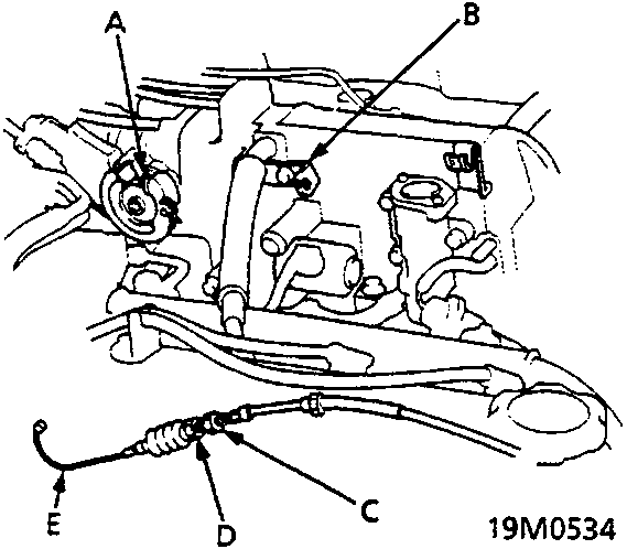
A Throttle linkage
B Cable bracket
C Adjusting nut
D Locknut
E Inner cable
- Fully open the throttle valve, then install the throttle cable in the throttle linkage and install the cable housing in the cable bracket.
- Warm up the engine to normal operating temperature (the radiator fan comes ON).
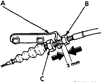
A Cable bracket
B Adjusting nut
C Locknut
- Hold the cable sheath, removing all slack from the cable.
- Turn the adjusting nut until it is 3 mm away from the cable bracket.
Parts & tools for this job For Rover 600
- PARTEngine gasket setSearch: Rover 600 engine gasket set
- TOOLTorque wrenchSearch: 3/8 inch torque wrench
- TOOLFeeler gauge setSearch: feeler gauge set
Links open Amazon search results in a new tab. As an Amazon Associate I earn from qualifying purchases.