
Fuel supply system
- Make
- Rover
- Model
- 600 Rover 600 Repair Manual - Volumes 1 and 2 - 2nd Edition
- Section
- Repairs › Fuel supply system
Engine management system – PGM-FiFuel supply system
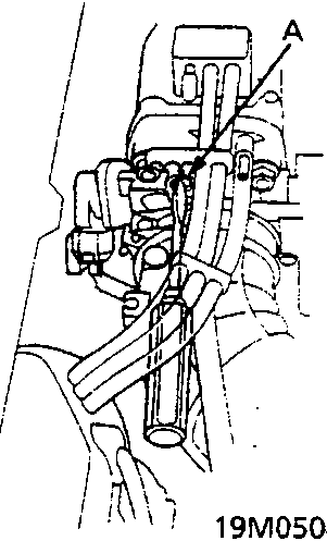
Note: (KS) Remove No. 10 (7.5 A) fuse in the passenger compartment fuse box, then check that the headlights and side marker lights are off.
The idle speed should be:| M/T | 770 ± 50 rpm |
|---|---|
| A/T | 770 ± 50 rpm (in N or P position) |
| M/T | 770 ± 50 rpm |
|---|---|
| A/T | 770 ± 50 rpm (in N or P position) |
| M/T | 770 ± 50 rpm |
|---|---|
| A/T | 770 ± 50 rpm (in N or P position) |
Note: If the idle speed is not within specification, see Idle control system Symptom Chart.
FUEL SUPPLY SYSTEM
Fuel Pressure
Relieve the fuel pressure as follows: WARNING:- Do not smoke while working on the fuel system.
Keep open flames or sparks away from your work area. - Be sure to relieve fuel pressure while the engine is off.
Note: Before disconnecting fuel pipes or hoses, release pressure from the system by loosening the 6 mm service bolt at the fuel rail.
1. Disconnect battery earth lead. 2. Remove fuel filler cap.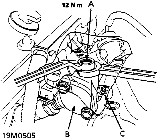
B Fuel rail
C Absorbent cloth 3. Position absorbent cloth around sealing bolt. Slacken bolt to relieve fuel pressure. Retighten bolt to 12 Nm.
Note:
- A fuel pressure gauge can be attached at the 6 mm sealing bolt hole.
- Always replace the washer between the sealing bolt and the special banjo bolt, whenever the sealing bolt is loosened to relieve fuel pressure.
- Replace all washers whenever the bolts are removed to disassemble parts.
Parts & tools for this job For Rover 600
- PARTEngine gasket setSearch: Rover 600 engine gasket set
- TOOLTorque wrenchSearch: 3/8 inch torque wrench
- TOOLFeeler gauge setSearch: feeler gauge set
Links open Amazon search results in a new tab. As an Amazon Associate I earn from qualifying purchases.