
Inspection/Adjustment
- Make
- Rover
- Model
- 600 Rover 600 Repair Manual - Volumes 1 and 2 - 2nd Edition
- Section
- Repairs › Inspection/Adjustment
Engine management system – PGM-FiInspection/Adjustment
Inspection/Adjustment
LHD:
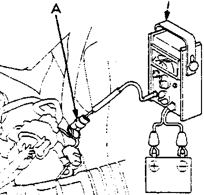
RHD:
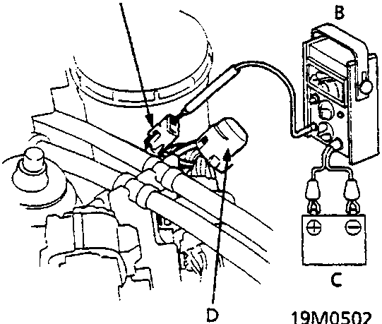
- A Test tachometer connector
- B Tachometer
- C Battery
- D Cap
- Start the engine and warm it up to normal operating temperature (the radiator fan comes on).
- Connect a tachometer.
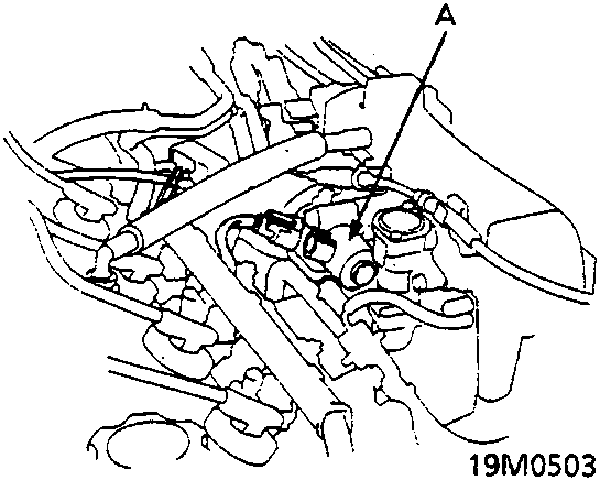
- A IAC valve
- Disconnect the 2P connector from the Idle Air Control (IAC) valve.
- Start the engine with the accelerator pedal slightly depressed. Stabilise the engine speed at 1000 rpm, then slowly release the pedal until the engine idles.
- Check idling in no – load conditions in which the headlights, blower fan, rear screen demister, radiator fan, and air conditioner are not operating.
Note: (KS) Remove No. 10 (7.5 A) fuse in the passenger compartment fuse box, then check that the headlights and side marker lights are off.
The idle speed should be:
| M/T | 620 ± 50 rpm |
| A/T | 620 ± 50 rpm (in N or P position) |
Parts & tools for this job For Rover 600
- PARTEngine gasket setSearch: Rover 600 engine gasket set
- TOOLTorque wrenchSearch: 3/8 inch torque wrench
- TOOLFeeler gauge setSearch: feeler gauge set
Links open Amazon search results in a new tab. As an Amazon Associate I earn from qualifying purchases.