
Front lower arm bushing replacement (page 3 of 8)
- Make
- Rover
- Model
- 600 Rover 600 Repair Manual - Volumes 1 and 2 - 2nd Edition
- Section
- Repairs
SuspensionFront lower arm bushing replacement · page 3 of 8
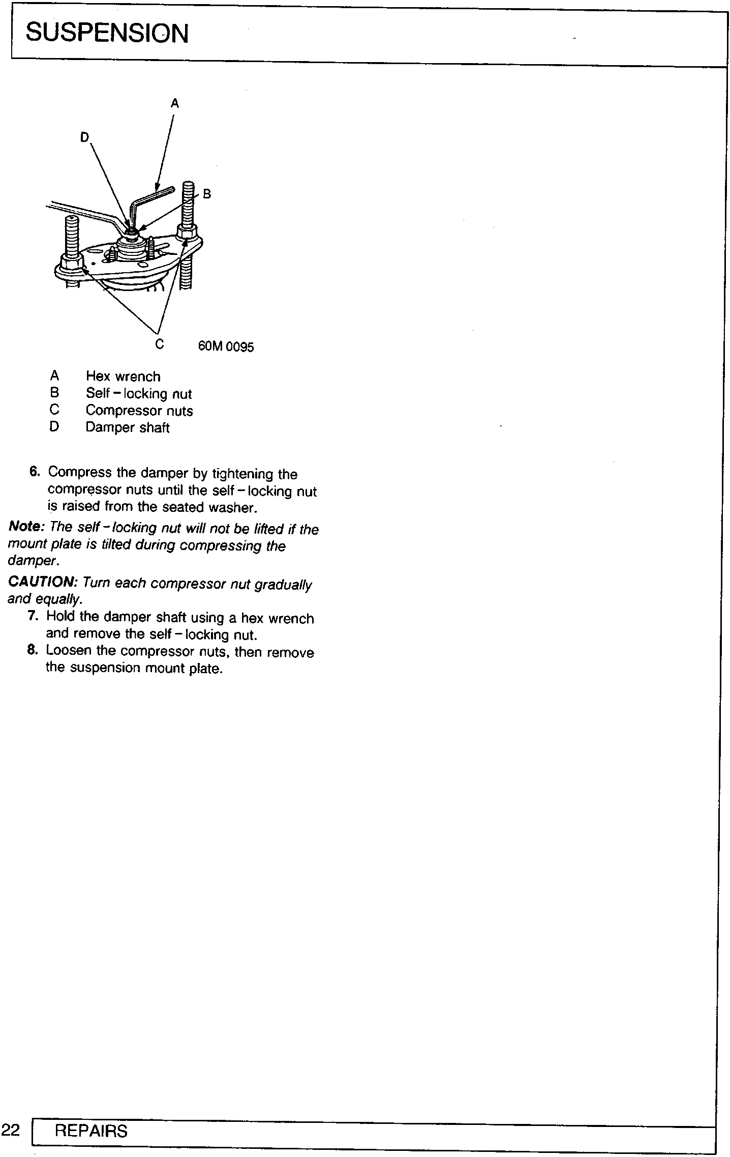
- A Hex wrench
- B Self-locking nut
- C Compressor nuts
- D Damper shaft
- Compress the damper by tightening the compressor nuts until the self-locking nut is raised from the seated washer.
Note: The self-locking nut will not be lifted if the mount plate is tilted during compressing the damper.
CAUTION: Turn each compressor nut gradually and equally.
- Hold the damper shaft using a hex wrench and remove the self-locking nut.
- Loosen the compressor nuts, then remove the suspension mount plate.
Parts & tools for this job For Rover 600
- TOOLCoil spring compressorSearch: coil spring compressor
- TOOLBall joint separatorSearch: ball joint separator
- PARTFront shock absorbersSearch: Rover 600 front shock absorbers
Links open Amazon search results in a new tab. As an Amazon Associate I earn from qualifying purchases.