
Front lower arm bushing replacement (page 6 of 8)
- Make
- Rover
- Model
- 600 Rover 600 Repair Manual - Volumes 1 and 2 - 2nd Edition
- Section
- Repairs
SuspensionFront lower arm bushing replacement · page 6 of 8
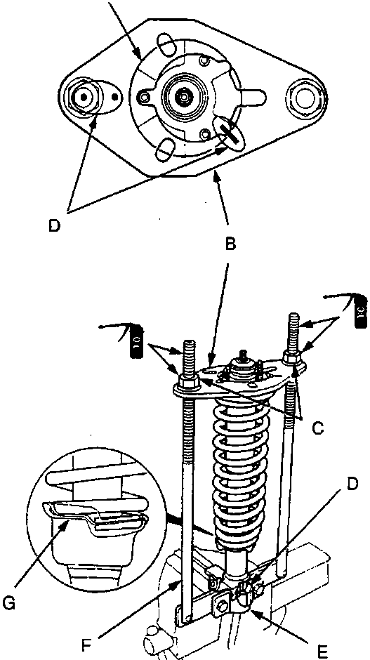
60M 0098
- A Damper mounting base
- B Suspension mount plate
- C Compressor nuts
- D Paint marks
- E Holder
- F Spring compressor
- G Spring lower seat
- Install the damper unit on the spring compressor by aligning the marks on the damper case and the spring compressor holder.
Note: If a new damper is to be installed, mark it on the same position as one the old damper.
- Reassemble the damper in reverse order of removal except the damper mounting washer and self – locking nut.
Note: Align the bottom of damper spring and spring lower seat as shown.
- Install the suspension mount plate on the damper with the mark on the plate facing painted threads.
- Position the damper mounting base by aligning the marks on the damper mounting base and mount plate.
- Apply oil to the seating surfaces of the compressor nuts and thread of the spring compressor, then loosely install the nuts.
- Compress the damper spring by turning the compressor nuts.
Note: Turn each compressor nut gradually and equally.
- Install the damper mounting washer, then loosely install the new self – locking nut.
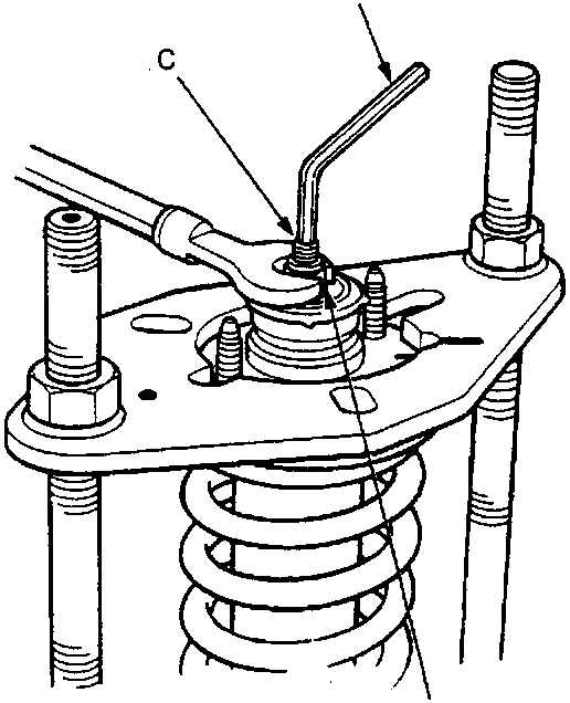
(30 Nm) 60M 0099
- A Hex wrench
- B Self locking nut
- C Damper shaft
- Hold the damper shaft using a hex wrench and tighten the self – locking nut.
- Remove the damper from the spring compressor.
Parts & tools for this job For Rover 600
- TOOLCoil spring compressorSearch: coil spring compressor
- TOOLBall joint separatorSearch: ball joint separator
- PARTFront shock absorbersSearch: Rover 600 front shock absorbers
Links open Amazon search results in a new tab. As an Amazon Associate I earn from qualifying purchases.