
Hub unit removal and wheel bearing replacement (page 3 of 5)
- Make
- Rover
- Model
- 600 Rover 600 Repair Manual - Volumes 1 and 2 - 2nd Edition
- Section
- Repairs
SuspensionHub unit removal and wheel bearing replacement · page 3 of 5
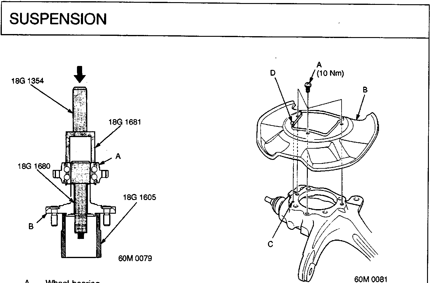
A Wheel bearing
B Front hub
A Screws
B Splash guard
C Hole
D Projection
Note: Wash the knuckle and hub thoroughly in high flash point solvent before reassembly.
- Press a new wheel bearing into the hub using the special tools and a press.
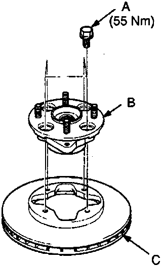
A Flange bolts
B Hub unit
C Brake disc
- Install the hub unit on the brake disc and tighten the flange bolts.
Note: Before installing the hub unit, clean the mating surfaces of the hub unit and brake disc.
- Install the splash guard, with projection aligned with hole and tighten the screws.
Note: Align the projection in the splash guard with the hole on the knuckle.
Parts & tools for this job For Rover 600
- PARTWheel bearingSearch: Rover 600 wheel bearing
- TOOLBearing puller kitSearch: wheel bearing puller kit
- PARTCV boot kitSearch: Rover 600 cv boot kit
Links open Amazon search results in a new tab. As an Amazon Associate I earn from qualifying purchases.