
Hub unit removal and wheel bearing replacement (page 4 of 5)
- Make
- Rover
- Model
- 600 Rover 600 Repair Manual - Volumes 1 and 2 - 2nd Edition
- Section
- Repairs
SuspensionHub unit removal and wheel bearing replacement · page 4 of 5
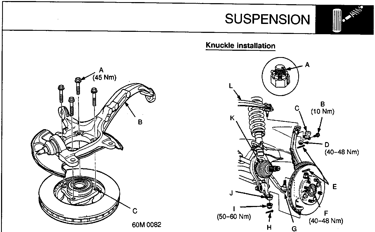
45 Nm
- Install the knuckle on the hub unit and tighten the self – locking bolts.
- A Self – locking bolt
- B Knuckle
- C Hub unit
- A Cotter pin
- B 6 mm Bolt
- C Knuckle protector
- D Castle nut
- E Cotter pins
- F Castle nut
- G Tie – rod end
- H Cotter pin
- I Castle nut
- J Lower arm
- K Drive shaft outboard joint
- L Upper arm
- Prior to knuckle installation, inspect the ball joint boot for damage or deterioration.
- Install the knuckle on the drive shaft outboard joint.
- Install the knuckle on the tie – rod end, upper arm and lower arm, then tighten the castle nuts and install the new cotter pins.
CAUTION: Torque the castle nut to the lower torque specification, then tighten sufficiently for alignment to the next available pin hole. Do not align the nut by loosening.
- Install the knuckle protector with the 6mm bolt.
Parts & tools for this job For Rover 600
- PARTWheel bearingSearch: Rover 600 wheel bearing
- TOOLBearing puller kitSearch: wheel bearing puller kit
- PARTCV boot kitSearch: Rover 600 cv boot kit
Links open Amazon search results in a new tab. As an Amazon Associate I earn from qualifying purchases.