
Suspension (page 7 of 7)
- Make
- Rover
- Model
- 600 Rover 600 Repair Manual - Volumes 1 and 2 - 2nd Edition
- Section
- Repairs
SuspensionSuspension · page 7 of 7
WARNING: The dampers contain nitrogen gas and oil under pressure. The pressure must be relieved before disposal to prevent explosion and possible injury when scrapping. Always wear eye protection to avoid getting metal shavings in your eyes when the gas damper pressure is relieved.
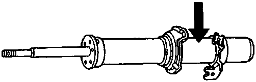
60M 0128
Front damper
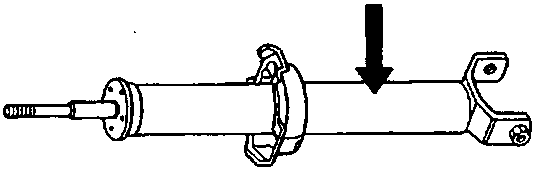
60M 0127
Rear damper
- Place the damper on a level surface with its rod extended and drill a hole of 2.0 – 3.0mm (0.08 – 0.12in) diameter in the body, at the point arrowed, to release the gas.
Parts & tools for this job For Rover 600
- TOOLCoil spring compressorSearch: coil spring compressor
- TOOLBall joint separatorSearch: ball joint separator
- PARTShock absorbersSearch: Rover 600 shock absorbers
Links open Amazon search results in a new tab. As an Amazon Associate I earn from qualifying purchases.