
Steering column operation
- Make
- Rover
- Model
- Coupé, Cabriolet & Tourer 200/400 Coupé, Cabriolet & Tourer Workshop Manual Supplement
- Section
- Description and operation › Steering column operation
STEERING COLUMN OPERATION
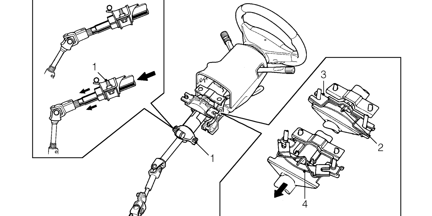
- Clamp - lower column
- Claw - upper column
The steering column contains a 2 piece collapsible steering shaft running in a bearing at its upper end and a bush at its base.
The steering column mountings are designed to deform and or move to absorb energy in the event of an impact. At its base, the clamp securing the column will allow it to slide when under load while at the opposite end of the column, a claw welded to the column engages upon an energy absorbing plate secured to the vehicle body. In the event of an impact, the column moves forward, bending the plate which absorbs energy as it deforms. Additional protection to the driver’s face and upper torso is provided by the SRS airbag in the centre of the steering wheel. In the event of frontal impact, if the vehicle is exceeding a set speed, the airbag will inflate.
- Energy absorbing plate (before)
- Energy absorbing plate (after)
The upper end of the column is supported by a single bolt, held captive in the bracket by a locking plate. Releasing the column adjustment lever slackens the nut securing this bolt and allows movement along the slots in the support bracket thus providing adjustment of the column height.
When the steering wheel is moved, the turning effort of the shaft is transmitted to the pinion shaft of the steering rack by an intermediate shaft mounted between two universal joints. These joints allow for adjustments made to the column position and for the movement of the column in an impact.
Parts & tools for this job For Rover Coupé, Cabriolet & Tourer
- TOOLTie rod end toolSearch: tie rod end puller
- TOOLBall joint separatorSearch: ball joint separator
- FLUIDPower steering fluidSearch: Rover power steering fluid
Links open Amazon search results in a new tab. As an Amazon Associate I earn from qualifying purchases.