
Power steering
- Make
- Rover
- Model
- Coupé, Cabriolet & Tourer 200/400 Coupé, Cabriolet & Tourer Workshop Manual
- Section
- Repairs › Power steering
Engine 1.4 K8Power steering
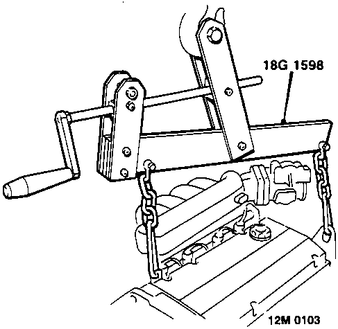
- Use a hoist and connect adjustable lifting bracket 18G 1598 to engine.
Raise hoist, take weight of engine without exerting lifting load on mounting bolts.
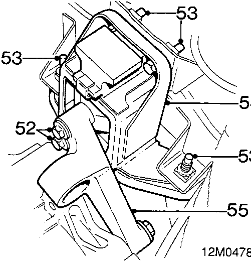
- Remove 2 bolts, gearbox mounting bracket to L.H. engine mounting.
- Remove 4 bolts, L.H. engine mounting to body.
- Lower engine and remove L.H. engine mounting
- Air conditioning: Remove 2 bolts, remove mounting bracket from gearbox.
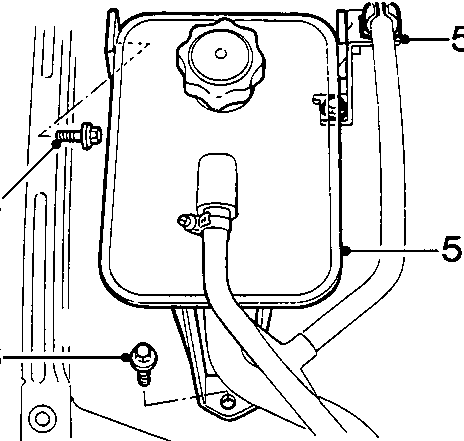
- Remove 3 bolts, expansion tank to body and bracket to body, position tank aside and release hose from clip.
- Power steering: Remove 2 bolts, power steering pipes to body, position pipes aside.
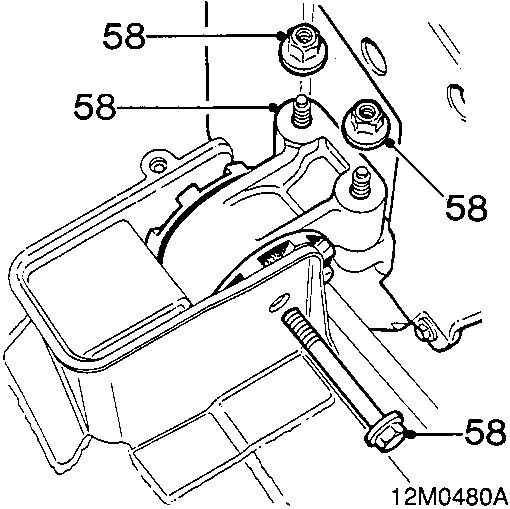
- Remove 2 nuts and through bolt from R.H. engine mounting, remove engine mounting.
- Position drain tray and pull engine forward.
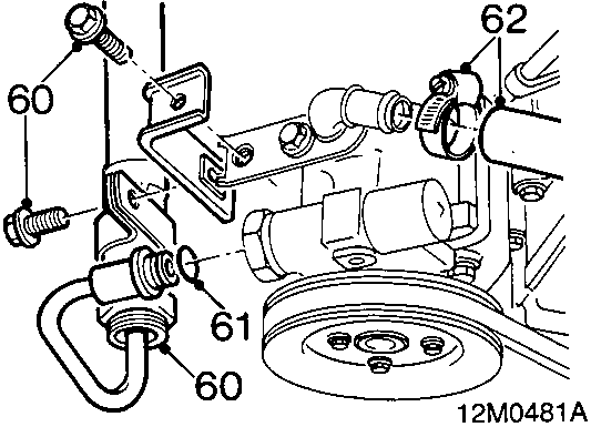
Power steering
- Remove 2 bolts and disconnect hose union and bracket from power steering pump.
- Remove 'O' ring from union.
- Disconnect return hose from power steering pump. Plug hoses and pump. Remove drain tray.
Parts & tools for this job For Rover Coupé, Cabriolet & Tourer
- TOOLTie rod end toolSearch: tie rod end puller
- TOOLBall joint separatorSearch: ball joint separator
- FLUIDPower steering fluidSearch: Rover power steering fluid
Links open Amazon search results in a new tab. As an Amazon Associate I earn from qualifying purchases.