
Refit
- Make
- Rover
- Model
- Coupé, Cabriolet & Tourer 200/400 Coupé, Cabriolet & Tourer Workshop Manual
- Section
- Repairs › Refit
Engine 1.4 K8Refit
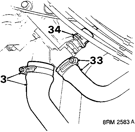
- Slacken clips and disconnect 2 coolant hoses from cylinder head.
- Disconnect multiplug from coolant sensor.
- Disconnect h.t. lead from distributor cap.
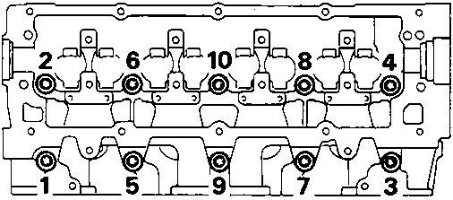
- Slacken 10 cylinder head to oil rail bolts in sequence shown. Remove bolts and store in fitted order.
- Remove cylinder head assembly from cylinder block, use assistance.
- Remove cylinder head gasket from cylinder block and discard.
CAUTION: Do not rotate crankshaft with cylinder head removed. Place cylinder head on blocks of wood to avoid damaging valves.
Refit
- Clean cylinder head and mating face, use foam action gasket removal spray and plastic scraper. Clean oil and coolant passages. Clean exhaust manifold and front pipe mating faces.
De – carbonise piston crowns and cylinder head if necessary. - Inspect cylinder head bolts, see Cylinder Head Bolts Inspection.
- Wash clean cylinder head bolts and wipe dry. Oil threads and under head of bolts.
- Fit new cylinder head gasket onto cylinder block.
- Fit cylinder head onto cylinder block carefully locating dowels, use assistance.
- Carefully enter cylinder head bolts, DO NOT DROP. Screw bolts into place by hand.
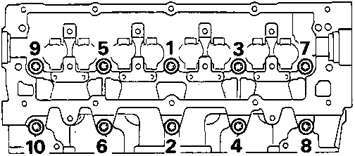
- Tighten cylinder head bolts progressively in sequence shown.
Cylinder head bolt tightening procedure:
All bolts to 20 Nm. Use a felt tip pen and mark position of radial mark on each bolt head.
Turn all bolts through 180°.
Turn all bolts through another 180° and align marks.
CAUTION: If bolt is overtightened, back off 90° and realign.
- Align and fit support stays to cylinder block, tighten bolts to 25 Nm.
- Connect harness to support stays.
- Connect multiplug to coolant sensor.
- Connect coil h.t. lead to distributor cap.
- Engage peg and connect brake vacuum hose to inlet manifold, tighten banjo bolt to 50 Nm.
- Connect 2 coolant hoses to cylinder head, tighten clips.
- Connect 2 coolant hoses to inlet manifold, tighten clips.
- Connect expansion tank hose to inlet manifold, tighten clip.
- Connect Lucar to inlet manifold heater and multiplug to coolant sensor.
- Connect multiplugs to injector, stepper motor and throttle potentiometer.
- Connect throttle inner cable to throttle cam and outer cable to abutment bracket.
Parts & tools for this job For Rover Coupé, Cabriolet & Tourer
- PARTEngine gasket setSearch: Rover Coupé, Cabriolet & Tourer engine gasket set
- TOOLTorque wrenchSearch: 3/8 inch torque wrench
- TOOLFeeler gauge setSearch: feeler gauge set
Links open Amazon search results in a new tab. As an Amazon Associate I earn from qualifying purchases.