
Remove (page 2 of 3)
- Make
- Rover
- Model
- Coupé, Cabriolet & Tourer 200/400 Coupé, Cabriolet & Tourer Workshop Manual
- Section
- Repairs
Engine 1.6Remove · page 2 of 3
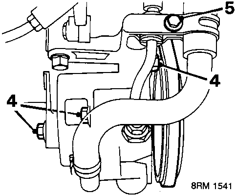
Power steering
- Remove 3 bolts securing power steering pump to bracket.
- Remove bolt securing power steering pipe clamp.
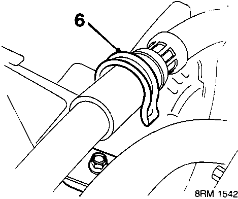
- Release power steering hose from clip.
- Release drive belt from pump pulley; move pump aside.
CAUTION: Keep pump upright to avoid fluid spillage.
All models
- Remove camshaft cover, see Camshaft Cover Gasket.
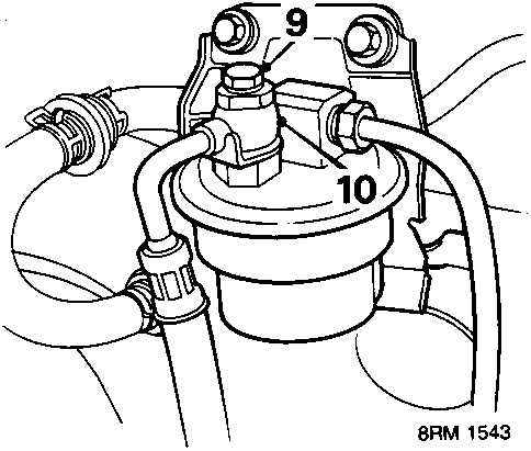
- Position absorbent cloth around sealing bolt. Slacken bolt to relieve fuel pressure. Retighten bolt to 12 Nm.
- Disconnect banjo union from fuel filter; collect 2 sealing washers.
CAUTION: Plug the connections.
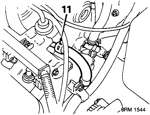
- Disconnect fuel return hose from fuel rail.
CAUTION: Plug the connections.
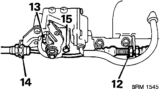
- Slacken throttle cable lock nut.
- Slide end of throttle cable out of bracket and throttle linkage.
- Automatic gearbox: Slacken nut on throttle control cable.
- Automatic gearbox: Release throttle control cable at lever.
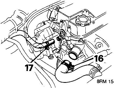
- Slacken clip, disconnect top hose from cylinder head.
- Slacken clip, disconnect heater hose from cylinder head.
Parts & tools for this job For Rover Coupé, Cabriolet & Tourer
- PARTEngine gasket setSearch: Rover Coupé, Cabriolet & Tourer engine gasket set
- TOOLTorque wrenchSearch: 3/8 inch torque wrench
- TOOLFeeler gauge setSearch: feeler gauge set
Links open Amazon search results in a new tab. As an Amazon Associate I earn from qualifying purchases.