
Remove
- Make
- Rover
- Model
- Coupé, Cabriolet & Tourer 200/400 Coupé, Cabriolet & Tourer Workshop Manual
- Section
- Repairs › Remove
Modular engine management system - MPiRemove
Service Repair No. Fuel rail – 19.60.04
Service Repair No. Injector – 19.60.10
Remove
Injectors
- Disconnect battery earth lead.
- Remove inlet manifold chamber, see MANIFOLD & EXHAUST – Repairs.
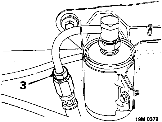
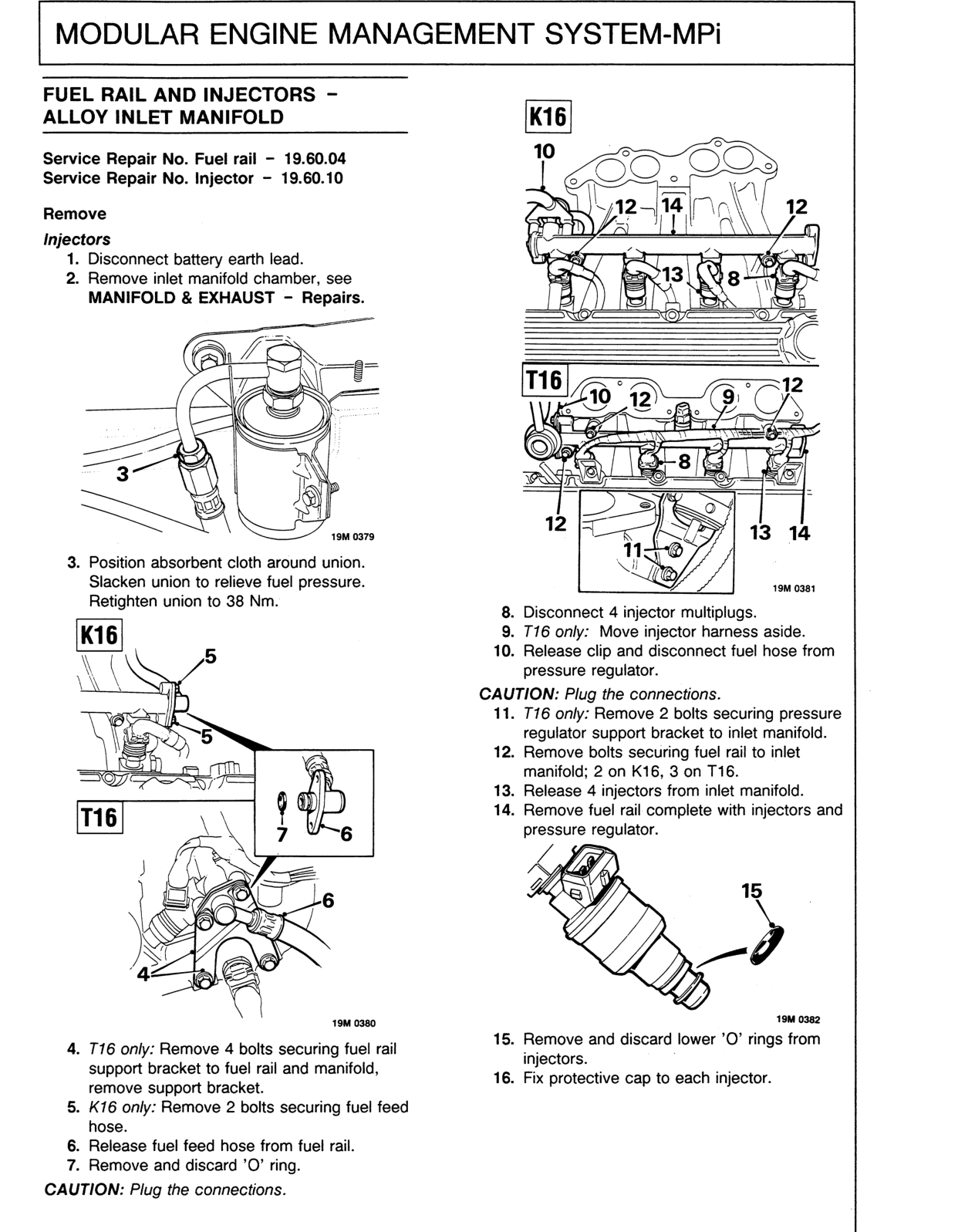
- Position absorbent cloth around union. Slacken union to relieve fuel pressure. Retighten union to 38 Nm.
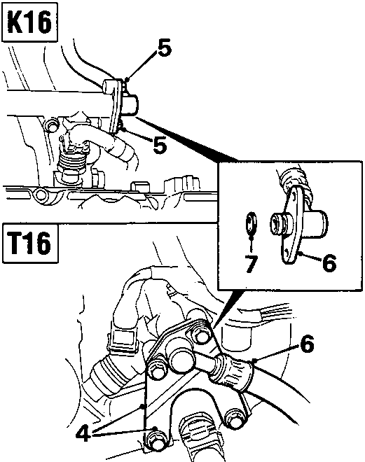
- T16 only: Remove 4 bolts securing fuel rail support bracket to fuel rail and manifold, remove support bracket.
- K16 only: Remove 2 bolts securing fuel feed hose.
- Release fuel feed hose from fuel rail.
- Remove and discard 'O' ring.
CAUTION: Plug the connections.
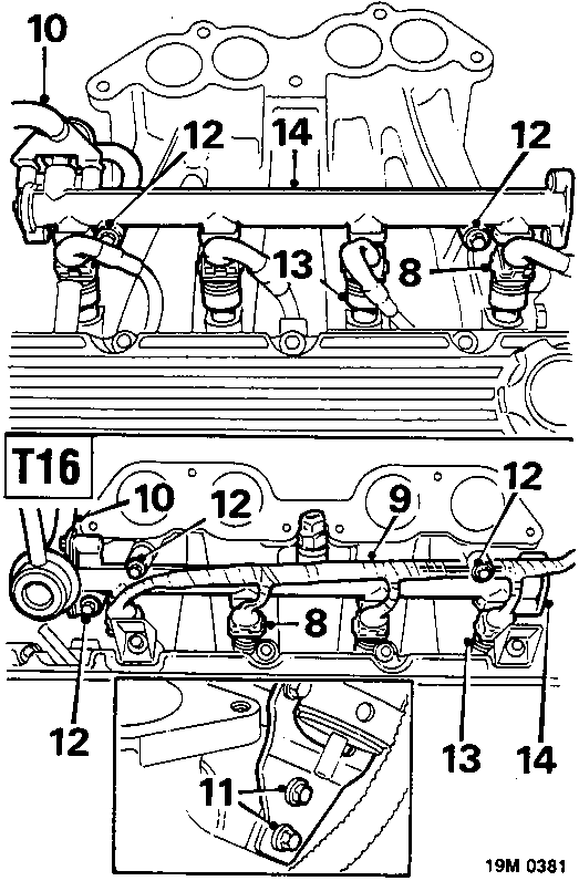
- Disconnect 4 injector multiplugs.
- T16 only: Move injector harness aside.
- Release clip and disconnect fuel hose from pressure regulator.
CAUTION: Plug the connections.
- T16 only: Remove 2 bolts securing pressure regulator support bracket to inlet manifold.
- Remove bolts securing fuel rail to inlet manifold; 2 on K16, 3 on T16.
- Release 4 injectors from inlet manifold.
- Remove fuel rail complete with injectors and pressure regulator.
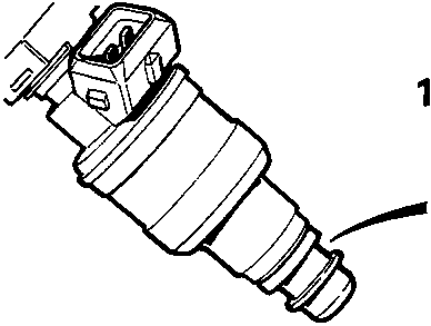
- Remove and discard lower 'O' rings from injectors.
- Fix protective cap to each injector.
Original page
Parts & tools for this job For Rover Coupé, Cabriolet & Tourer
- PARTEngine gasket setSearch: Rover Coupé, Cabriolet & Tourer engine gasket set
- TOOLTorque wrenchSearch: 3/8 inch torque wrench
- TOOLFeeler gauge setSearch: feeler gauge set
Links open Amazon search results in a new tab. As an Amazon Associate I earn from qualifying purchases.