
Remove
- Make
- Rover
- Model
- Coupé, Cabriolet & Tourer 200/400 Coupé, Cabriolet & Tourer Workshop Manual
- Section
- Repairs › Remove
Modular engine management system - MPiRemove
Service Repair No. 19.22.16
Remove
- Naturally aspirated models: Remove radiator block, see COOLING SYSTEM – Repairs.
- Turbo models: Remove intercooler.
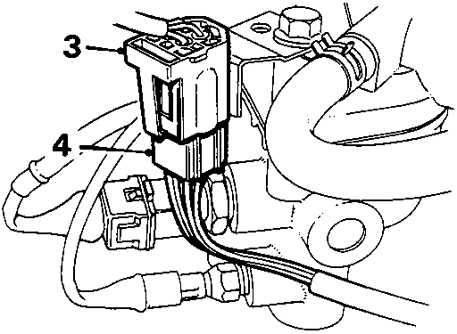
- Release multiplug from bracket.
- Disconnect oxygen sensor multiplug.
- Release harness lead from tie.
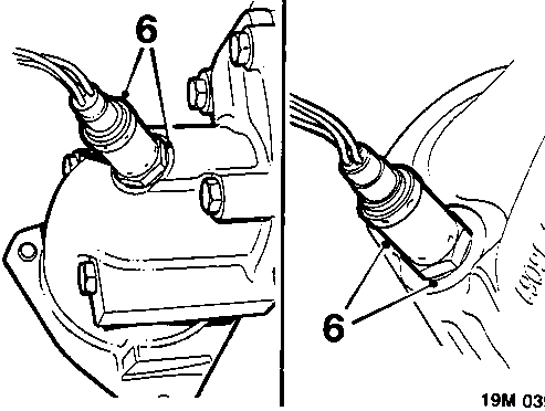
- Remove oxygen sensor; collect sealing washer.
Refit
- Fit sealing washer to oxygen sensor.
- Fit oxygen sensor and tighten to 55 Nm.
- Naturally aspirated models: Secure multiplug in bracket, connect multiplug.
- Air conditioned models: Secure harness lead in tie.
- Naturally aspirated models: Fit radiator block, see COOLING SYSTEM – Repairs.
- Turbo models: Fit intercooler.
THROTTLE POTENTIOMETER – ALLOY INLET MANIFOLD
Service Repair No. 18.30.17
Remove
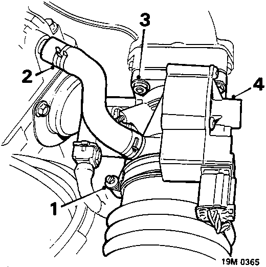
Naturally aspirated model illustrated
T16 only
- Slacken clip and disconnect intake hose from throttle housing.
- Disconnect breather hose from camshaft cover.
- Remove 4 nuts securing throttle housing to inlet manifold.
- Withdraw throttle housing to gain access to throttle potentiometer.
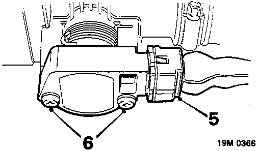
All models
- Disconnect throttle potentiometer multiplug.
- Remove 2 screws securing throttle potentiometer, remove potentiometer.
Parts & tools for this job For Rover Coupé, Cabriolet & Tourer
- PARTEngine gasket setSearch: Rover Coupé, Cabriolet & Tourer engine gasket set
- TOOLTorque wrenchSearch: 3/8 inch torque wrench
- TOOLFeeler gauge setSearch: feeler gauge set
Links open Amazon search results in a new tab. As an Amazon Associate I earn from qualifying purchases.