
Audio amplifier operation check
- Make
- Fiat
- Model
- 500 Factory Service Manual
- Year
- 2007–2024
- Section
- Accessories › Audio amplifier operation check
AUDIO AMPLIFIER OPERATION CHECK
| STEP | CHECK TO BE PERFORMED | REMEDIAL ACTION IF THE CHECK IS NOT OK |
|---|---|---|
| 1 | Check audio amplifier input signals (14-way connector A) Turn the radio on and tune into a station with a steady signal that can be heard properly and, using the Examiner in voltmeter ambient, connect the probs to pins 1 and 7 (right front audio input) Select a 20V end of scale and 5 seconds on the Examiner, then press the start button All the figures that appear should be evaluated with a tolerance of about 20%; the image should be similar to the one below Repeat the test connecting to the following pins:
| Restore the wiring between the radio and the amplifier. If the radio audio output signals are interrupted (even through the supply is okay) replace the radio |
| 2 | Check the audio amplifier input signals (10-way connector B) Repeat the test as described in step 1 connecting to the following pins:
| Restore the wiring between the radio and the audio amplifier. If the radio audio output signals are interrupted (even through the supply is okay) replace the radio |
| 3 | Check the audio amplifier output signals (10-way connector B) Repeat the test as described in step 1 connecting to the following pins:
| Restore the continuity/insulation for the wiring for the audio signals between the audio amplifier and the speakers. If no faults were detected during the previous check and the audio signal is interrupted at the amplifier output, replace the amplifier Op. 5570T36 |
| 4 | Earth check Disconnect connector B for the audio amplifier Connect using an ohmmeter between pin 2 of connector B and an earth and check that the resistance is less than 1 Ohm | Restore earth connection |
| 5 | Check the power supply for the subwoofer amplifier enablement Turn the ignition key to the ON position, switch the radio on and connect between pin 8 of connector B of the audio amplifier and an earth and check for the presence of a voltage of about 12 Volt | Restore the continuity of the wiring between the radio and the amplifier |
| 6 | Check power supply +30 Connect between pin 1 of connector B of the amplifier and earth and check for the presence of a voltage of around 12 Volt | Restore the continuity of the wiring between the engine compartment junction unit and the amplifier Renew fuse F02 in the engine compartment junction unit after having identified the cause of the break |
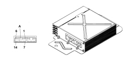
| Connector A | |
|---|---|
| Pin | Function |
| 1 | Right front audio input (-) |
| 2 | Left front audio input (-) |
| 3 | N.C. |
| 4 | Left rear audio output (+) |
| 5 | Left front audio output (-) |
| 6 | Left front audio output (+) |
| 7 | Right front audio input (+) |
| 8 | Left front audio input (+) |
| 9 | N.C. |
| 10 | Right front audio output (-) |
| 11 | Right front audio output (+) |
| 12 | Right rear audio output (-) |
| 13 | Right rear audio output (+) |
| 14 | Left front audio output (-) |
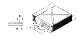
| Connector B | |
|---|---|
| Pin | Function |
| 1 | +30 |
| 2 | Chassis earth |
| 3 | Right rear audio input (-) |
| 4 | Left rear audio input (-) |
| 5 | N.C. |
| 6 | N.C. |
| 7 | N.C. |
| 8 | Subwoofer enablement |
| 9 | Right rear audio input (+) |
| 10 | Left rear audio input (+) |
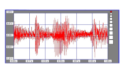
Amplifying the graphic trend of the voltage, the signal displayed should be similar to the following
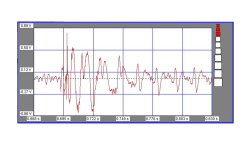
The presence of this graph, displayed at the subwoofer input, shows that the audio signal is arriving correctly.
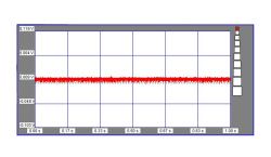
This graph shows an interrupted signal
Parts & tools for this job For 2007 Fiat 500
- TOOLDigital multimeterSearch: automotive digital multimeter
- PARTAssorted fuse kitSearch: car fuse assortment kit
- TOOLWire crimper and connector kitSearch: wire crimper connector kit
Links open Amazon search results in a new tab. As an Amazon Associate I earn from qualifying purchases.