
Crankcase vapour/gas recirculation system
- Make
- Fiat
- Model
- 500 Factory Service Manual
- Year
- 2007–2024
- Section
- Emission control system › Crankcase vapour/gas recirculation system
CRANKCASE VAPOUR/GAS RECIRCULATION SYSTEM
The system controls the emission of breather gases from the crankcase that are made up of a mixture of air, fuel vapours and burnt gases that seep through the piston seals and of lubricant oil vapours, drawing them back into the engine where they are burnt by the engine.
The breather gases coming from the crankcase go as far as the cylinder head and are then directed (1) into two different intakes:
- with the accelerator throttle opening medium-high, the gases are drawn in by the duct immediately downstream of the air filter (2);
- with small throttle openings (and, in particular, with the engine idling or in deceleration conditions) the gases are drawn in downstream of the throttle (3).
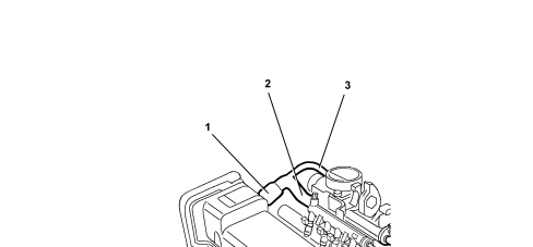
SPECIFICATIONS
Function
The oil vapour emissions are controlled by means of an oil separator (1) which collects the vapours coming from the crankcase and from the timing cover via the pipe (2). The condensed vapours return to the sump, via a pipe (3), whilst the uncondensed vapours are sent, via a pipe (4) to the turbocharger air inlet hose.
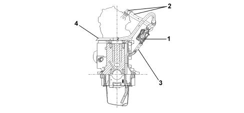
1. Oil separator
2. Cover oil vapour outlet
3. Condensed vapour sump return
4. Inlet vapour delivery pipe
The oil vapour separator is illustrated in the diagram below.
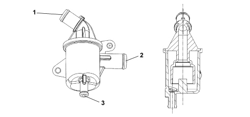
1. Collection of oil vapours from cover
2. Oil vapour outlet to intake manifold
3. Condensed oil vapour outlet to crankcase
Parts & tools for this job For 2007 Fiat 500
- PARTExhaust gasketSearch: Fiat 500 2007 exhaust gasket
- TOOLPenetrating oilSearch: penetrating oil
- TOOLOBD2 scannerSearch: OBD2 scanner
Links open Amazon search results in a new tab. As an Amazon Associate I earn from qualifying purchases.