
Upstream lambda sensor operation check
- Make
- Fiat
- Model
- 500 Factory Service Manual
- Year
- 2007–2024
- Section
- Emission control system › Upstream lambda sensor operation check
UPSTREAM LAMBDA SENSOR OPERATION CHECK
| STEP | CHECK TO BE PERFORMED | REMEDIAL ACTION IF THE CHECK IS NOT OK |
|---|---|---|
| 1 | Upstream sensor heater signal check Let the engine warm up and reach operating temperature Prepare the Examiner diagnostic equipment to download a voltage graph. Select the VOLTMETER function from the INSTRUMENT menu with the time set at 10 seconds. Connect the probes between pins 3 and 4 of the sensor connector. Bring the engine up to 3000 rpm and keep this speed constant for the entire download Press the START button on the diagnostic equipment to begin downloading a graph. Check that the signal corresponds to the attached graph | Move on to Step 2 |
| 2 | Upstream sensor resistance check Disconnect the negative battery lead Disconnect the sensor connector Measure between terminals 3 and 4 and check that the sensor heater resistance is between 6 and 8 Ohm at 20°C and still less than 70 Ohm at higher temperatures. Check the continuity/insulation of the wiring between the sensor and the engine control unit See E5030 PETROL ENGINES ELECTRONIC MANAGEMENT Move on to Step 3 | Replace the upstream Lambda sensor Op. 1080B94 FRONT LAMBDA SENSOR TO WITH CATALYTIC CONVERTER - R.R Restore correct wiring |
| 3 | Upstream sensor resistance wiring check Check the continuity of the wiring between pin 1 of the sensor and pin 11 of the engine control unit Check the continuity of the wiring between pin 2 of the sensor and pin 57 of the engine control unit Move on to Step 4 | Restore the correct wiring. Replace the engine control unit |
| 4 | Upstream sensor signal check Prepare the Examiner diagnostic equipment to download a voltage graph. Select the VOLTMETER function from the INSTRUMENT menu with the time set at 10 seconds. Check that there is an oscillogram as illustrated in the attached graph between terminals 1 and 2 of the downstream sensor connector | Move on to Step 5 |
| 5 | Upstream sensor oxygen signal wiring check Check the continuity of the wiring between the sensor and the engine control unit | Restore the correct wiring. |

Sensor connector
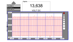
Heater signal
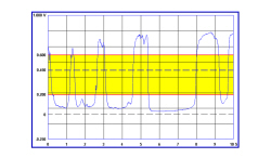
Sensor oxygen signal
Parts & tools for this job For 2007 Fiat 500
- PARTOxygen sensorSearch: Fiat 500 2007 oxygen sensor
- TOOLOxygen sensor socketSearch: oxygen sensor socket
- TOOLOBD2 scannerSearch: OBD2 scanner
Links open Amazon search results in a new tab. As an Amazon Associate I earn from qualifying purchases.