
Front end assembly - r.r.
- Make
- Fiat
- Model
- Grande Punto Factory Service Manual
- Year
- 2005–2012
- Section
- Removing-refitting › Front end assembly - r.r.
FRONT END ASSEMBLY - R.R.
Removing
Op. 7055B54 UNDER ENGINE PROTECTION/GUARD - R.R.
Op. 7210A18 R.R FRONT CROSSMEMBER
Op. 5540B07 LEFT FRONT HEADLAMP - R.R
Op. 5540B08 RIGHT FRONT HEADLAMP - R.R
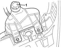
1. Remove the engine coolant system expansion reservoir cap.
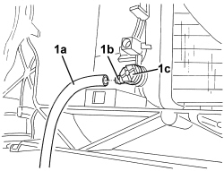
1. Insert rubber pipe (1a) on engine coolant drain cock (1b), then open cock (1c) and allow the fluid to flow out into a container.
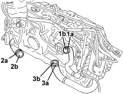
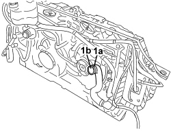
1. Loosen collar (1a) and disconnect end (1b) of the lower sleeve from the radiator.
2. Loosen collar (2a) and disconnect end (2b) of the air outlet sleeve from the intercooler.
3. Loosen collar (3a) and disconnect end (3b) of the flexible hose from the turbine to the rigid pipe.
- Lower the vehicle.
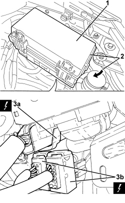
1. Undo the retainers and remove the cover of the junction box in the engine compartment.
2. Slightly turn the box to gain access to the underlying electrical connections.
3. Disconnect the electrical connections (3a, 3b).
| Description | Component |
|---|---|
| REAR/CROSSMEMBER COUPLING | See D106 REAR/CROSSMEMBER COUPLING |
| JUNCTION UNIT | See B001 JUNCTION UNIT |
1. Disconnect the electrical earth lead on the front left side of the side panel.
| Description | Component |
|---|---|
| LEFT FRONT EARTH | See C010 LEFT FRONT EARTH |
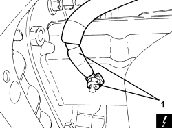
1. Disconnect the electrical connection from the air conditioning system multi-stage linear sensor.
| Description | Component |
|---|---|
| LINEAR SENSOR FOR FANS | See K120 LINEAR SENSOR FOR FANS |
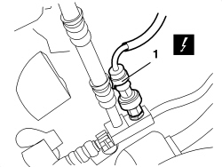
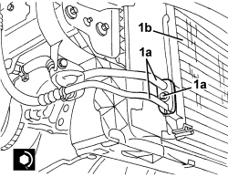
1. Undo the bolt (1a) and disconnect the pipe (1b) from the air conditioner condenser (1c).
Seal the connectors that have been disconnected using suitable plugs to prevent dampness and impurities from entering the system.
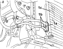
1. Disconnect the bonnet release cable from the lock.
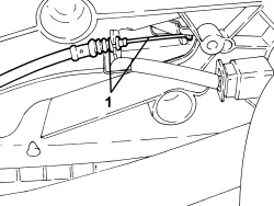
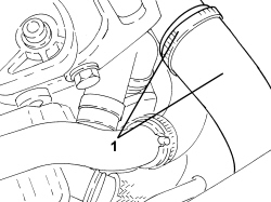
1. Loosen the collar and disconnect the sleeve from the engine cooling system thermostat.
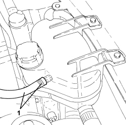
1. Loosen the collar and disconnect the sleeve from the engine cooling system expansion tank.
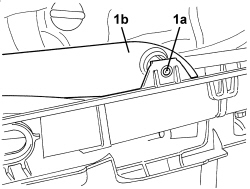
1. Undo the bolt (1a) and move cold air intake (2b) slightly aside.
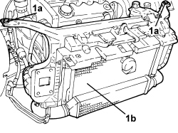
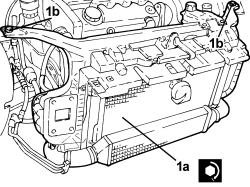
1. Unscrew bolts (1a) and remove the front end unit (1b) complete with:
- expansion tank
- heat exchanger
- bonnet lid lock
- fans
- crossmember wiring
- sleeves and rigid pipes
- If necessary, strip the front end, remove the following parts with reference to the appropriate procedures:
- expansion tank
- heat exchanger
- bonnet lid lock
- fans
- crossmember wiring
- sleeves and rigid pipes
Refitting
- Check that the front end is not damaged.
- If necessar, refit the various components on the front end.
1. Position the front end (1a) and secure it using the bolts (1b).
| Component | Fastening | dia | Value (daNm) | Validity |
|---|---|---|---|---|
| Front end to bodyshell | Bolt | M10x1.5x28.5 | 3.2 ÷ 3.8 |
- Fit the cold air intake.
- Connect the sleeve to the expansion tank and secure with a collar.
- Connect the sleeve to the thermostat and secure with a collar.
- Connect the bonnet release cable.
1. Position pipe (1a) on air conditioner compressor (1b) and secure with bolt (1c).
| Component | Fastening | dia | Value (daNm) | Validity |
|---|---|---|---|---|
| Pipe connector on condenser | Bolt | M8 | 1.8 ÷ 2.2 |
- Connect the electrical connection of the linear sensor, of the side panel earth and of the intermediate junctions.
- Refit the engine compartment junction unit and fit the bonnet lid.
- Connect the intercooler and radiator pipes.
- Close the screw plug and keep the coolant drainage pipe.
- Refill the cooling circuit and tighten the cap on the expansion reservoir.
Op. 5540B08 RIGHT FRONT HEADLAMP - R.R
Op. 5540B07 LEFT FRONT HEADLAMP - R.R
Op. 7210A18 R.R FRONT CROSSMEMBER
Op. 7055B54 UNDER ENGINE PROTECTION/GUARD - R.R.
Removing
Op. 7210A18 R.R FRONT CROSSMEMBER
Op. 5540B07 LEFT FRONT HEADLAMP - R.R
Op. 5540B08 RIGHT FRONT HEADLAMP - R.R
1. Remove the engine coolant system expansion reservoir cap.
1. Insert rubber pipe (1a) on engine coolant drain cock (1b), then open cock (1c) and allow the fluid to flow out into a container.
1. Loosen collar (1a) and disconnect end (1b) of the lower sleeve from the radiator.
- Lower the vehicle.
1. Undo the retainers and remove the cover of the junction box in the engine compartment.
2. Slightly turn the box to gain access to the underlying electrical connections.
3. Disconnect the electrical connections (3a, 3b).
| Description | Component |
|---|---|
| REAR/CROSSMEMBER COUPLING | See D106 REAR/CROSSMEMBER COUPLING |
| JUNCTION UNIT | See B001 JUNCTION UNIT |
1. Disconnect the electrical earth lead on the front left side of the side panel.
| Description | Component |
|---|---|
| LEFT FRONT EARTH | See C010 LEFT FRONT EARTH |
1. Disconnect the electrical connection from the air conditioning system linear sensor.
| Description | Component |
|---|---|
| LINEAR SENSOR FOR FANS | See K120 LINEAR SENSOR FOR FANS |
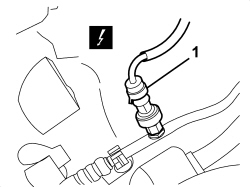
1. Undo the bolt (1a) and disconnect the pipe (1b) from the air conditioner condenser (1c).
Seal the connectors that have been disconnected using suitable plugs to prevent dampness and impurities from entering the system.
1. Disconnect the bonnet release cable from the lock.
1. Loosen the collar (1a) and disconnect the sleeve (1b) from the engine cooling system thermostat.
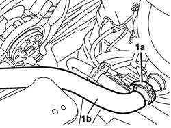
1. Loosen the collar and disconnect the sleeve from the engine cooling system expansion tank.
1. Undo the bolt (1a) and move cold air intake (2b) slightly aside.
1. Unscrew bolts (1a) and remove the front end unit (1b) complete with:
- expansion tank
- heat exchanger
- bonnet lid lock
- fans
- crossmember wiring
- sleeves and rigid pipes
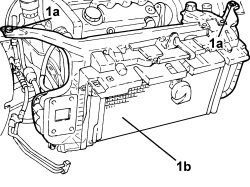
- If necessary, strip the front end, remove the following parts with reference to the appropriate procedures:
- expansion tank
- heat exchanger
- bonnet lid lock
- fans
- crossmember wiring
- sleeves and rigid pipes
Refitting
- Check that the front end is not damaged.
- If necessar, refit the various components on the front end.
1. Position the front end (1a) and secure it using the bolts (1b).
| Component | Fastening | dia | Value (daNm) | Validity |
|---|---|---|---|---|
| Front end to bodyshell | Bolt | M10x1.5x28.5 | 3.2 ÷ 3.8 |
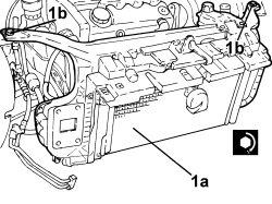
- Fit the cold air intake.
- Connect the sleeve to the expansion tank and secure with a collar.
- Connect the sleeve to the thermostat and secure with a collar.
- Connect the bonnet release cable.
1. Position pipe (1a) on air conditioner compressor (1b) and secure with bolt (1c).
| Component | Fastening | dia | Value (daNm) | Validity |
|---|---|---|---|---|
| Pipe connector on condenser | Bolt | M8 | 1.8 ÷ 2.2 |
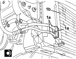
- Connect the electrical connection of the linear sensor, of the side panel earth and of the intermediate junctions.
- Refit the engine compartment junction unit and fit the bonnet lid.
- Connect the intercooler and radiator pipes.
- Close the screw plug and keep the coolant drainage pipe.
- Refill the cooling circuit and tighten the cap on the expansion reservoir.
Op. 5540B08 RIGHT FRONT HEADLAMP - R.R
Op. 5540B07 LEFT FRONT HEADLAMP - R.R
Parts & tools for this job For 2005 Fiat Grande Punto
- TOOLTrim removal tool kitSearch: trim removal tool kit
- PARTTouch-up paintSearch: Fiat touch up paint
- PARTPanel clip assortmentSearch: Fiat panel clips assortment
Links open Amazon search results in a new tab. As an Amazon Associate I earn from qualifying purchases.