
Refit throttle position (tp) sensor
- Make
- Land Rover
- Model
- Defender 90 Workshop Manual (NAS)
- Section
- Repair › Refit throttle position (tp) sensor
Fuel systemRefit throttle position (tp) sensor
Refit THROTTLE POSITION (TP) SENSOR
- Position throttle linkage and spring to plenum Service repair no - 19.22.49 chamber.
- Fit spring to linkage. Remove
- Hold throttle open to gain access to mounting bolts.
- Fit and tighten mounting bolts to 8 Nm, 6 lbf ft.
- Clean mating faces of TP sensor and plenum chamber.
- Fit TP sensor and engage spindle.
- Fit clamping plate and tighten bolts to 2 Nm, 1.5 lbf ft.
- Clean mating faces of IACV and plenum chamber.
- Fit gasket to IACV.
- Fit IACV to plenum chamber and tighten bolts to 2 Nm, 1.5 lbf ft.
- Clean mating faces of water jacket and plenum chamber.
- Position gasket to plenum chamber.
- Fit water jacket to plenum chamber and tighten bolts to 13 Nm, 10 lbf ft.
- Remove cloth from ram housing.
- Clean plenum and inlet manifold mating faces.
- Position plenum chamber.
- Connect coolant hoses to plenum chamber.
- Tighten hose clips.
- Loosen and remove hose clamp.
- Remove cloth.
Remove
- Apply a thin, uniform coating of Loctite 577 sealant to sealing face of plenum chamber.
- Fit plenum chamber and tighten bolts to 24 Nm, 18 lbf ft.
- Connect multiplug to TP sensor.
- Connect multiplug to IACV.
- Connect breather hose to plenum chamber.
- Connect purge hose to plenum chamber.
- Fit kick down cable to abutment bracket, fit locknut and adust cable. See AUTOMATIC GEARBOX, Adjustment, Kickdown cable adjustment
- Connect throttle cable to abutment bracket.
- Align throttle cable to lever, fit clevis pin and secure with new split pin.
- Align kick down cable to lever.
- Fit and secure clevis pin.
- Connect air intake hose and secure with clip.
- Reconnect battery negative lead.
- Top up cooling system.
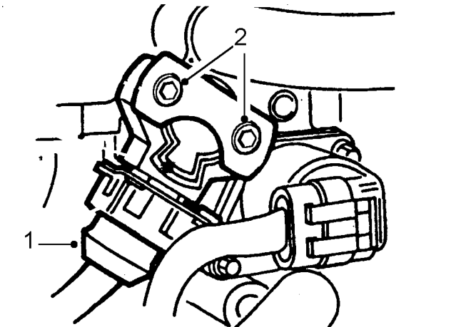
- Disconnect multiplug from TP sensor.
- Remove 2 screws securing TP sensor and collect clamp plate.
- Remove TP sensor.
- Clean TP sensor and mating face.
- Fit sensor ensuring drive engages with throttle spindle.
- Position clamp plate, fit screws and tighten to 2 Nm, 1.5 lbf ft.
- Connect multiplug.
Parts & tools for this job For Land Rover Defender
- TOOLOBD2 scannerSearch: OBD2 scanner
- TOOLDigital multimeterSearch: automotive digital multimeter
- TOOLBack-probe test leadsSearch: back probe test leads
Links open Amazon search results in a new tab. As an Amazon Associate I earn from qualifying purchases.