
Engine and gearbox assembly (page 6 of 9)
- Make
- Rover
- Model
- 100 Repair Manual Supplement
- Year
- 1996–1998
- Section
- Repairs
EngineEngine and gearbox assembly · page 6 of 9
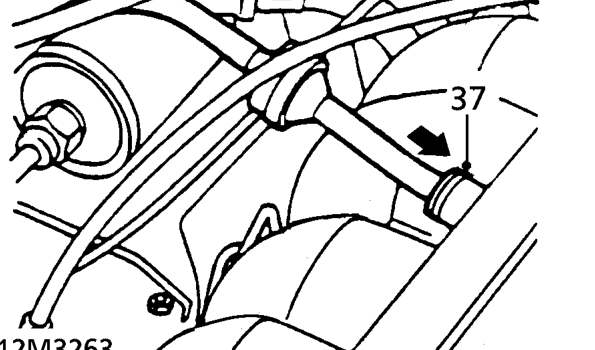
- Depress plastic collar and disconnect brake servo hose from inlet manifold.
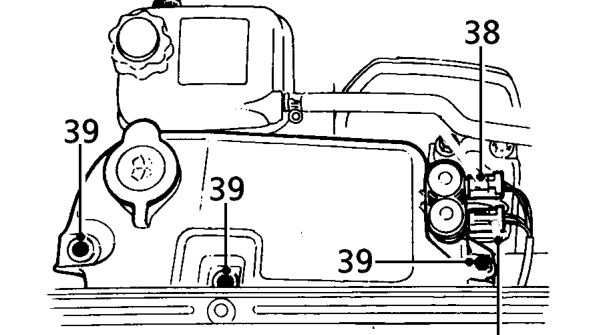
- Disconnect 2 multiplugs from washer pumps.
- Remove 3 screws securing washer reservoir and move reservoir aside.
- Raise front of vehicle.
WARNING: Support on safety stands.
- Remove starter motor. See REPAIR MANUAL - Electrical.
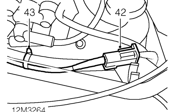
- Release and disconnect oxygen sensor multiplug.
- Remove clip securing oxygen sensor lead to engine harness.
- Disconnect exhaust front pipe from manifold. See MANIFOLD & EXHAUST SYSTEMS, Repairs.
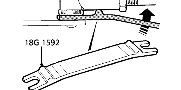
- Using tool 18G 1592, disconnect gear change linkage ball joint from lower selector lever.
Parts & tools for this job For 1996 Rover 100
- PARTEngine gasket setSearch: Rover 100 1996 engine gasket set
- TOOLTorque wrenchSearch: 3/8 inch torque wrench
- TOOLFeeler gauge setSearch: feeler gauge set
Links open Amazon search results in a new tab. As an Amazon Associate I earn from qualifying purchases.