
Workshop Manuals Factory service & repair Rover
01 Information02 General data03 Engine04 Engine management system – PGM-Fi05 Cooling system, manifold and exhaust06 Clutch07 Manual gearbox08 Automatic gearbox09 Drive shafts10 Differential – manual gearbox11 Differential – automatic gearbox12 Steering13 Suspension14 Brakes and ABS15 Brakes – ABS BY416 Body17 Heating and ventilation18 Electrical19 Supplementary restraint system (SRS)
Rover Rover 600 Repair Manual - Volumes 1 and 2 - 2nd Edition14 · Brakes and ABS
14 · Brakes

Master cylinder (page 4 of 5)

Make
Rover
Model
600 Rover 600 Repair Manual - Volumes 1 and 2 - 2nd Edition
Section
Brakes: repairs
Brakes and ABSMaster cylinder · page 4 of 5
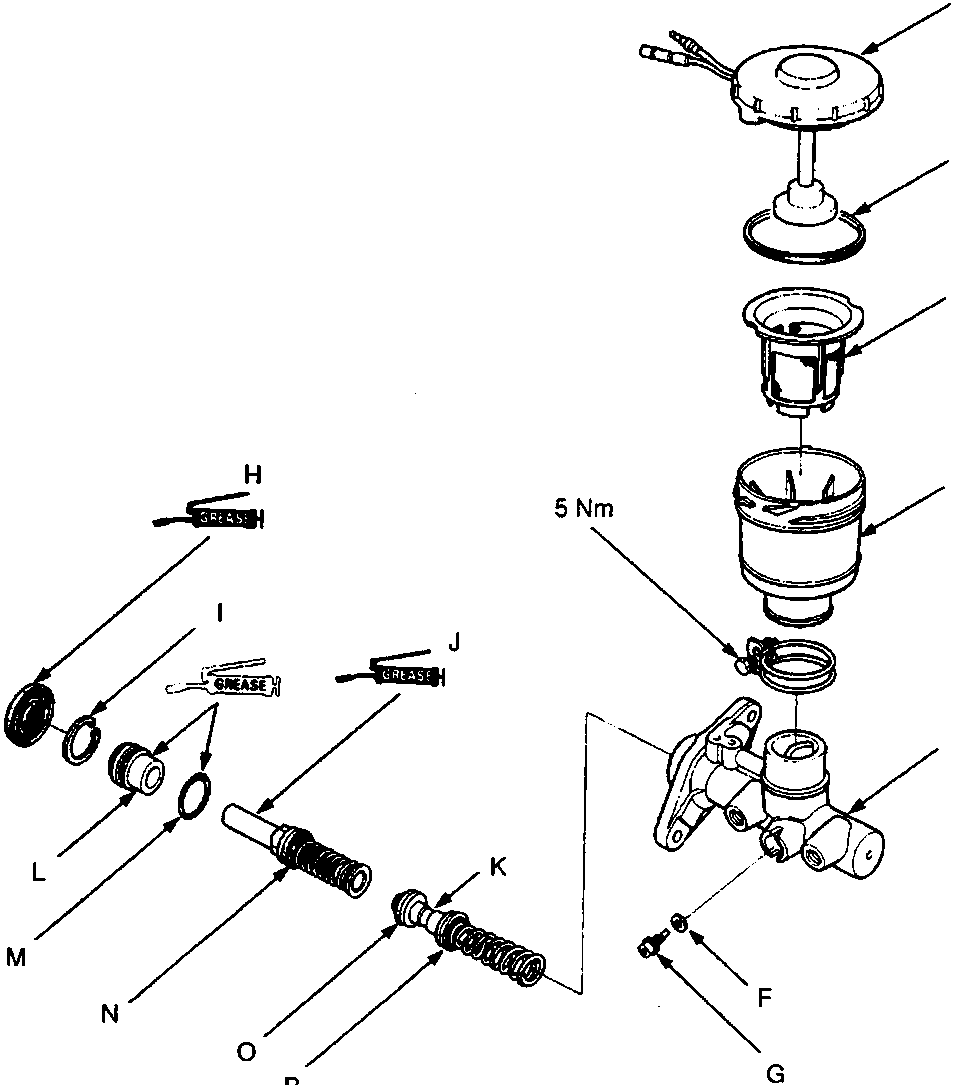
Exploded view diagram of a master cylinder assembly showing components labeled A through P, including reservoir, pistons, seals, and bolts. Torque values 5 Nm and (9 Nm) are indicated on specific fasteners. Grease icons are shown near several sealing components. The figure number 70M 0238 is printed at the bottom right.
  1. Reservoir cap
  2. Reservoir seal
  3. Strainer
  4. Reservoir
  5. Master cylinder
  6. Sealing washer
  7. Stop bolt
  8. Rod seal
  9. Circlip
  10. Secondary piston assembly
  11. Primary piston assembly
  12. Piston guide
  13. O-Ring
  14. Piston cup
  15. Pressure cup
  16. Piston cup

Parts & tools for this job For Rover 600

Links open Amazon search results in a new tab. As an Amazon Associate I earn from qualifying purchases.