
Original page (page 4 of 5)
- Make
- Rover
- Model
- 600 Rover 600 Repair Manual - Volumes 1 and 2 - 2nd Edition
- Section
- Brakes: repairs
Brakes and ABSOriginal page · page 4 of 5
Original page (page 4 of 5) – diagram from the Brakes and ABS chapter of the Rover Rover 600 Repair Manual - Volumes 1 and 2 - 2nd Edition factory manual.
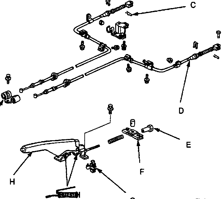
- A Clip
- B Clevis pin
- C Lock pin
- D Parking brake cable
- E Adjusting nut
- F Equaliser
- G Switch
- H Parking brake lever
- I Bracket
Parts & tools for this job For Rover 600
- PARTBrake padsSearch: Rover 600 brake pads
- TOOLBrake bleeder kitSearch: one man brake bleeder kit
- FLUIDBrake fluidSearch: brake fluid
Links open Amazon search results in a new tab. As an Amazon Associate I earn from qualifying purchases.