
Replacement (page 2 of 3)
- Make
- Rover
- Model
- 600 Rover 600 Repair Manual - Volumes 1 and 2 - 2nd Edition
- Section
- Repairs
Heating and ventilationReplacement · page 2 of 3
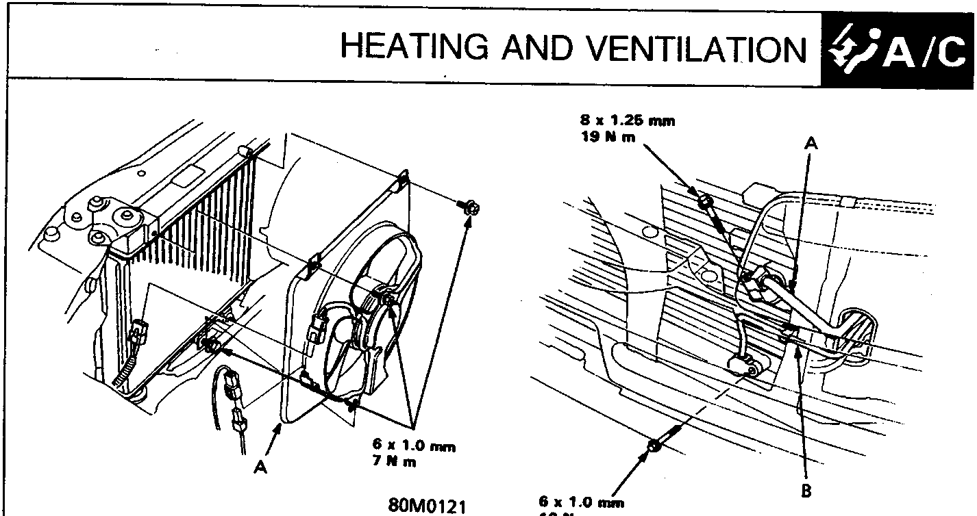
A Condenser fan shroud
A Discharge line
B Condenser line
- Disconnect the condenser fan shroud.
Remove the compressor connector from the condenser fan shroud, then disconnect the compressor connector.
Loosen the lower mounting bolt and remove the two upper mounting bolts, then remove the condenser fan shroud.
CAUTION: Do not damage the radiator fins when removing the condenser fan shroud.
- Remove the four bolts and the radiator upper mount brackets.
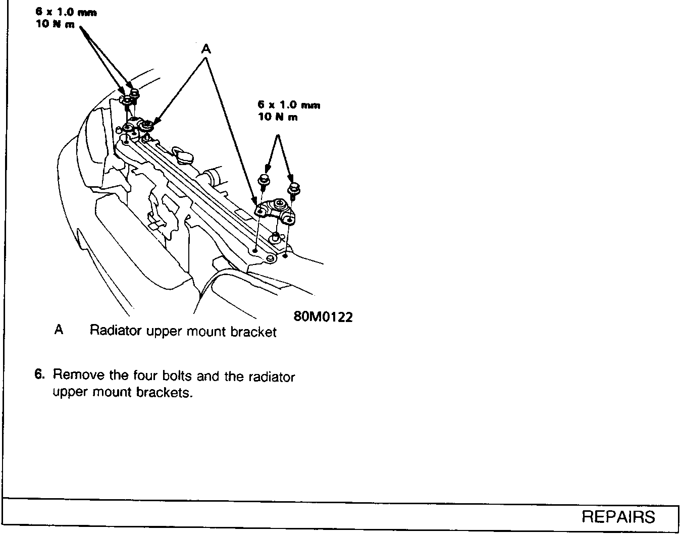
A Radiator upper mount bracket
- Remove the bolt and disconnect the condenser line from the condenser.
Remove the bolt and disconnect the discharge line from the condenser.
Note: Plug or cap the lines immediately after disconnecting, to avoid moisture and dust contamination into the system.
Parts & tools for this job For Rover 600
- TOOLA/C manifold gauge setSearch: AC manifold gauge set
- TOOLUV leak detection kitSearch: AC UV leak detection kit
- PARTCabin filterSearch: Rover 600 cabin filter
Links open Amazon search results in a new tab. As an Amazon Associate I earn from qualifying purchases.