
Replacement (page 3 of 3)
- Make
- Rover
- Model
- 600 Rover 600 Repair Manual - Volumes 1 and 2 - 2nd Edition
- Section
- Repairs
Heating and ventilationReplacement · page 3 of 3
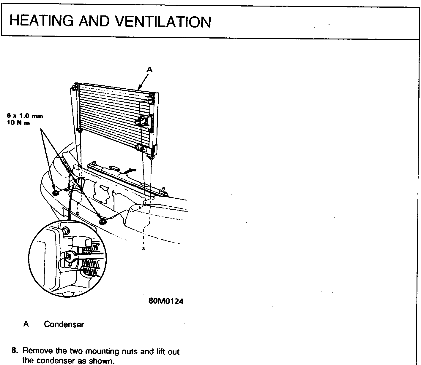
10 N m
A Condenser
- Remove the two mounting nuts and lift out the condenser as shown.
CAUTION:
- Do not damage the radiator and condenser fins when removing the condenser.
- Be careful not to drop the mounting nuts.
- Install in the reverse order of removal, and:
- If installing a new condenser, add refrigerant oil (Nippondenso Densoil 8).
- replace the 'O' rings with new ones at each fitting and apply a thin coat of refrigerant oil (Nippondenso Densoil 8) prior to installation.
Note: Be sure to use the correct 'O' rings for R134a to avoid leakage.
- do not damage the radiator or condenser fins when installing the condenser.
- be sure to install the condenser mount cushions securely into the holes.
- charge the system and test its performance.
Parts & tools for this job For Rover 600
- TOOLA/C manifold gauge setSearch: AC manifold gauge set
- TOOLUV leak detection kitSearch: AC UV leak detection kit
- PARTCabin filterSearch: Rover 600 cabin filter
Links open Amazon search results in a new tab. As an Amazon Associate I earn from qualifying purchases.