
Inspection (page 3 of 3)
- Make
- Rover
- Model
- 600 Rover 600 Repair Manual - Volumes 1 and 2 - 2nd Edition
- Section
- Repairs
Manual gearboxInspection · page 3 of 3
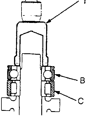
A Press
B Ball bearing
C Needle bearing
- Install the needle bearing.
- Install the ball bearing using a special tool and a press as shown.
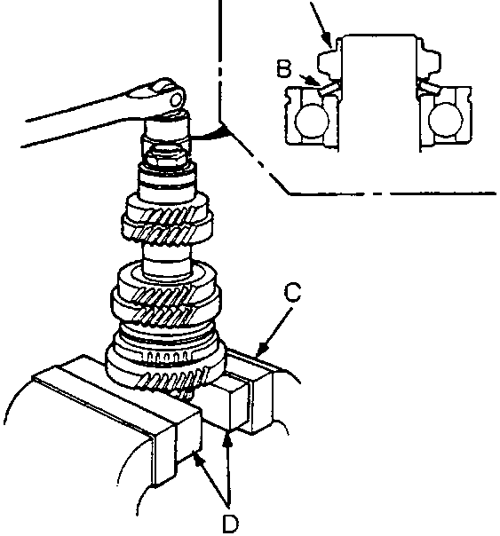
A Locknut.
B Spring washer
C Bench vice
D Wood blocks
- Install the spring washer.
- Securely clamp the countershaft assembly in a bench vice with wood blocks.
- Tighten the new locknut to the correct torque, then stake the locknut tab into the groove.
Parts & tools for this job For Rover 600
- PARTClutch kitSearch: Rover 600 clutch kit
- TOOLClutch alignment toolSearch: clutch alignment tool
- FLUIDGear oilSearch: Rover 600 manual gearbox oil
Links open Amazon search results in a new tab. As an Amazon Associate I earn from qualifying purchases.