
Air intake system (Engine management system - EDC)
- Make
- Rover
- Model
- 800 Workshop Manual
- Year
- 1996–1999
- Section
- Description and operation › Air intake system
AIR INTAKE SYSTEM
The engine is supplied with pre-compressed air by a single stage turbocharger.
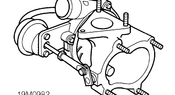
With the engine running, exhaust gases pass into the turbine side of the turbocharger causing the turbine to rotate, driving a compressor mounted on the turbine shaft in the intake side of the turbocharger.
Intake air is drawn through the air cleaner to the turbocharger, where it is compressed by the compressor. The compressed air is then fed into the inlet manifold via an intercooler, which reduces the temperature of the compressed air, increasing its density.
Boost control
Boost control is achieved by a pneumatic actuator operating a mechanical flap situated in the turbocharger which, when operated, allows exhaust gases to bypass the turbine side of the turbocharger, so decreasing the rotational speed of the turbine thereby reducing the pressure of the intake air.
The pneumatic actuator consists of a diaphragm connected to a mechanical linkage which is opposed by an internal spring. Pressure from the compressor side of the turbocharger is applied to the pneumatic actuator via a sensing pipe. The pressure acting on the pneumatic actuator diaphragm builds up until it exceeds the opposing force of the internal spring (approx. 1.2 Bar or 17 lb/in) causing the mechanical linkage to move, thereby opening the flap on the turbocharger and so reducing the boost pressure. As boost pressure is reduced the mechanical linkage will move the other way closing the flap on the turbocharger allowing the pressure to increase again. With the engine under load the pneumatic actuator will be constantly opening and closing the flap on the turbocharger.
Parts & tools for this job For 1996 Rover 800
- PARTGlow plugsSearch: Rover 800 1996 glow plugs
- TOOLGlow plug socketSearch: glow plug socket
- TOOLDiesel compression testerSearch: diesel compression tester
Links open Amazon search results in a new tab. As an Amazon Associate I earn from qualifying purchases.