
Throttle position sensor (Engine management system - EDC)
- Make
- Rover
- Model
- 800 Workshop Manual
- Year
- 1996–1999
- Section
- Description and operation › Throttle position sensor
Throttle position sensor
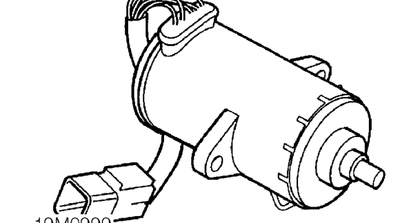
The engine management system is a ’Drive by Wire’ system. The throttle pedal is not physically connected to the fuel injection pump by a mechanical linkage as in a traditional injection system, but instead the amount of fuel injected is controlled by the ECM. The throttle pedal is connected by a cable to a throttle position sensor. Movements of the throttle pedal are sensed by the throttle position sensor and a signal sent to the ECM.
The throttle position sensor consists of a thick film potentiometer together with a sender switch. With the throttle pedal at rest the switch is open. When the throttle pedal has been moved enough to rotate the potentiometer more than 9 degrees the switch closes. The sender switch signal from the potentiometer is used by the ECM to check the operation of the circuit, implement idle speed control and over-run fuel shut-off.
When the potentiometer is moved the sender switch signals a logic input to the ECM. The ECM then checks the voltage signal from the potentiometer. This voltage is compared with a pre-programmed value to check the potentiometer is working correctly.
Throttle pedal movement causes voltage across the potentiometer to vary. The control unit calculates the rate of change of the voltage signal in positive (acceleration) or negative (deceleration) directions. From this the ECM can determine the required engine speed, rate of acceleration or rate of deceleration and apply acceleration enrichment, deceleration fuel metering or over-run fuel shut-off.
The ECM calculates the ’maximum allowable fuel quantity’ from the input signal according to strategies such as smoke limitation, active surge damping, fuel reduction to calculate the final figure. If the signal from the throttle potentiometer is smaller than the maximum allowable quantity then the requested quantity will be injected. However, if the requested quantity is greater than the maximum allowable quantity, then the maximum allowable quantity will be injected rather than that demanded.
Brake pedal switch

The brake pedal switch informs the ECM when the vehicle is braking and allows it to implement active surge damping and over-run fuel shut-off.
The ECM has two brake inputs, each of opposite polarity. Comparison of the two polarity states provides the ECM with brake sense. If both switches are the same polarity the ECM senses a fault.
Parts & tools for this job For 1996 Rover 800
- TOOLOBD2 scannerSearch: OBD2 scanner
- TOOLDigital multimeterSearch: automotive digital multimeter
- TOOLBack-probe test leadsSearch: back probe test leads
Links open Amazon search results in a new tab. As an Amazon Associate I earn from qualifying purchases.