
Refit
- Make
- Rover
- Model
- Coupé, Cabriolet & Tourer 200/400 Coupé, Cabriolet & Tourer Workshop Manual
- Section
- Screens › Refit
BodyRefit · page 1 of 2
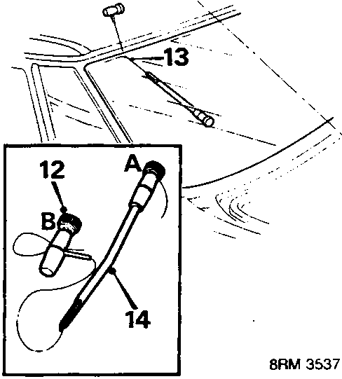
- Prepare cutting wire in handle A. Bend end of wire to handle and tape over end.
- Force cutting wire through sealer from inside and 100 mm from a top corner.
- Attach handle B. Allow 200 mm of wire between handles, bend end of wire to handle and tape over end.
- With an assistant, wedge tube of handle A between glass and flange and carefully cut sealer from flange using a straight pull along the glass from outside. At corners, use a sawing action.
- Attach suction cups to glass and lift glass from body
WARNING: If glass has broken: Use a vacuum cleaner to remove glass splinters.
Refit
- Carefully cut old sealer on body flange to obtain a smooth surface 2 mm thick. Remove old dam from flange without damaging paint surface.
- Original glass: Carefully cut back old sealer to obtain a smooth surface without damaging painted surface. Remove old dam material from glass.
CAUTION: Lay glass on felt covered supports, do not stand on edge. Any chipping of glass edge may develop into cracks.
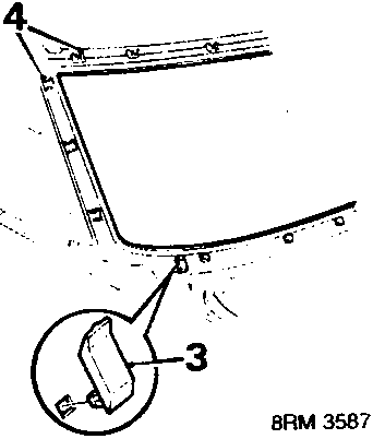
- Fit 2 stopper brackets to body.
- Renew any damaged moulding clips and holders.
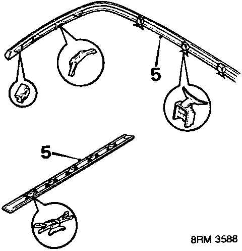
- Position clips in side and lower mouldings as shown.
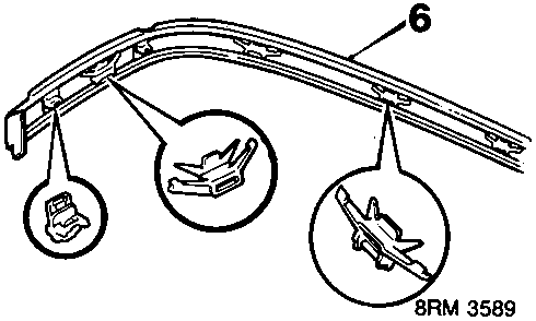
- Position clips in upper mouldings as shown.
Parts & tools for this job For Rover Coupé, Cabriolet & Tourer
- TOOLTrim removal tool kitSearch: trim removal tool kit
- PARTTouch-up paintSearch: Rover touch up paint
- PARTPanel clip assortmentSearch: Rover panel clips assortment
Links open Amazon search results in a new tab. As an Amazon Associate I earn from qualifying purchases.