
Models with air conditioning (page 2 of 2)
- Make
- Rover
- Model
- Coupé, Cabriolet & Tourer 200/400 Coupé, Cabriolet & Tourer Workshop Manual
- Section
- Repairs
Engine 1.4 K8Models with air conditioning · page 2 of 2
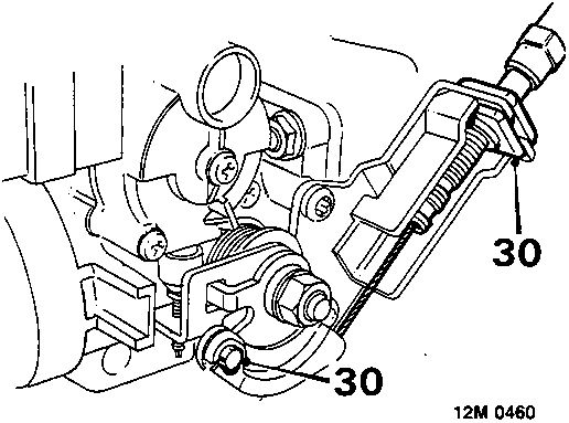
- Disconnect throttle cable from throttle cam and bracket, position aside.
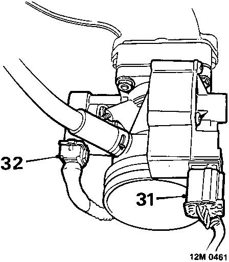
- Disconnect multiplug from stepper motor.
- Disconnect multiplug from throttle potentiometer.
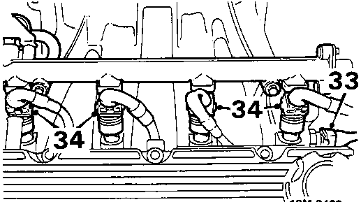
- Disconnect multiplug from intake air temperature sensor.
- Disconnect 4 multiplugs from injectors.
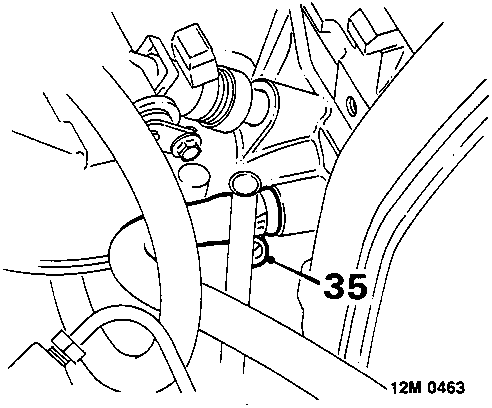
- Slacken clip and disconnect expansion tank hose from inlet manifold.
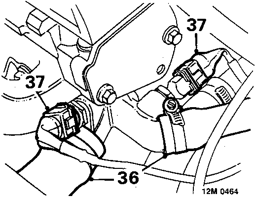
- Slacken clips and disconnect 2 coolant hoses from cylinder head.
- Disconnect 2 multiplugs from coolant sensors.
- Disconnect h.t. lead from distributor cap.
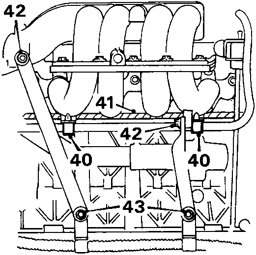
- Release fuel return hose from clips on manifold.
- Remove 2 bolts securing engine harness to inlet manifold.
- Release engine harness from around inlet manifold, position aside.
- Remove 2 bolts securing support stays to inlet manifold and manifold chamber.
Parts & tools for this job For Rover Coupé, Cabriolet & Tourer
- TOOLA/C manifold gauge setSearch: AC manifold gauge set
- TOOLUV leak detection kitSearch: AC UV leak detection kit
- PARTCabin filterSearch: Rover Coupé, Cabriolet & Tourer cabin filter
Links open Amazon search results in a new tab. As an Amazon Associate I earn from qualifying purchases.