
8RM 2329 (page 4 of 6)
- Make
- Rover
- Model
- Coupé, Cabriolet & Tourer 200/400 Coupé, Cabriolet & Tourer Workshop Manual
- Section
- Repairs
Engine 1.6 D.O.H.C.8RM 2329 · page 4 of 6
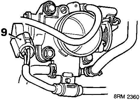
- Disconnect throttle angle sensor multiplug from throttle housing.
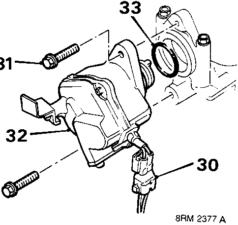
- Disconnect T.D.C. sensor multiplug.
- Remove 2 bolts T.D.C. sensor to cylinder head.
- Remove T.D.C. sensor.
- Discard 'O' ring.
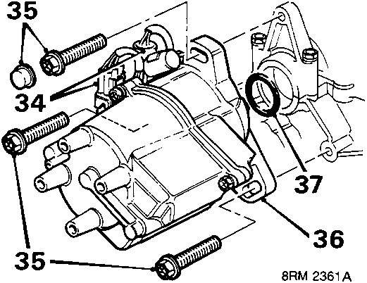
- Release 2 distributor multiplugs from restraining bracket and disconnect multiplugs.
- Remove 3 bolts distributor to cylinder head.
Note: Catalyst equipped engine: Remove tamper proof cap from top bolt.
- Remove distributor.
- Discard 'O' ring.
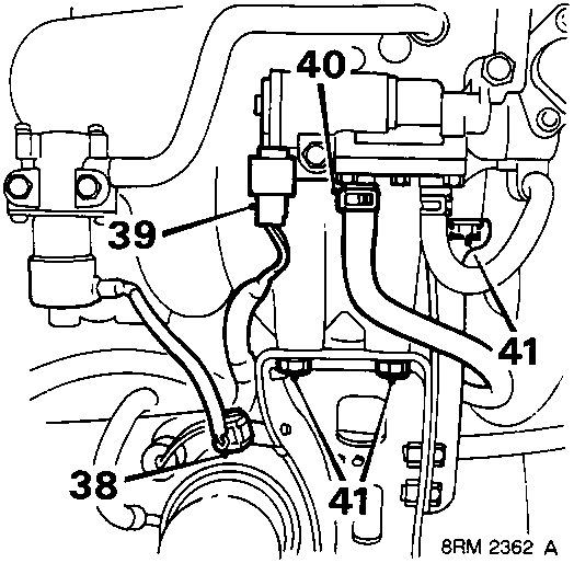
- Release fast idle solenoid multiplug from clip on support bracket and and disconnect multiplug.
- Disconnect multiplug from air control valve.
- Release clip and disconnect coolant rail hose from air control valve.
- Remove 3 bolts, support bracket to inlet manifold.
- Disconnect exhaust front pipe from manifold, see MANIFOLD & EXHAUST – Repairs.
- Remove starter motor, see ELECTRICAL – Repairs
- Remove camshaft timing belt.
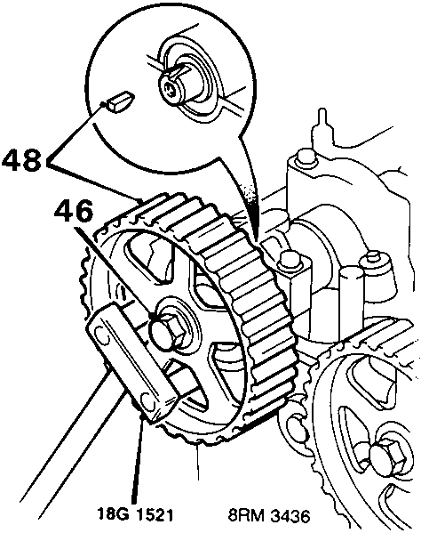
- Fit tool 18G 1521, to hold camshaft gears against rotation.
- Remove bolt and special washer from each camshaft gear.
- Remove tool 18G 1521.
- Remove camshaft gear and key from each camshaft.
Parts & tools for this job For Rover Coupé, Cabriolet & Tourer
- PARTEngine gasket setSearch: Rover Coupé, Cabriolet & Tourer engine gasket set
- TOOLTorque wrenchSearch: 3/8 inch torque wrench
- TOOLFeeler gauge setSearch: feeler gauge set
Links open Amazon search results in a new tab. As an Amazon Associate I earn from qualifying purchases.