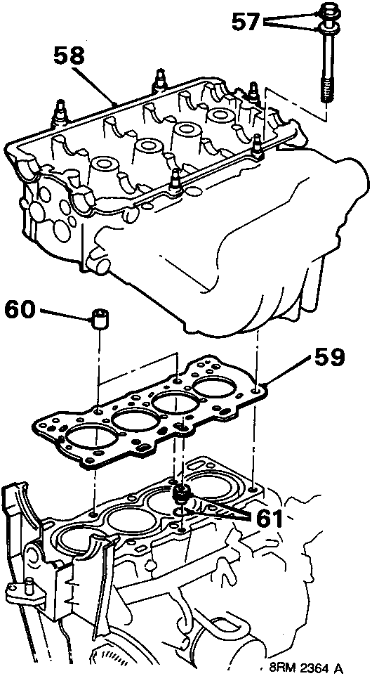
57. Remove 10 bolts and special washers.
58. Using assistance, lift cylinder head, complete with manifolds, off the cylinder block.
59. Discard cylinder head gasket.
60. Ensure that 2 locating dowels are in position in cylinder block.
61. Remove oil control jet and discard 'O' ring.
Refit
1. Using liquid gasket removal spray, thoroughly clean cylinder head and cylinder block mating surfaces.
2. Fit a new 'O' ring to oil control jet. Fit jet to cylinder block.
3. Position new gasket on cylinder block.
CAUTION: Gasket must be fitted dry.
4. Using assistance, carefully lower cylinder head onto cylinder block ensuring that dowels are correctly located in head.
5. Ensure cylinder head bolts are clean.
6. Apply clean engine oil to each cylinder head bolt and to the special washers.
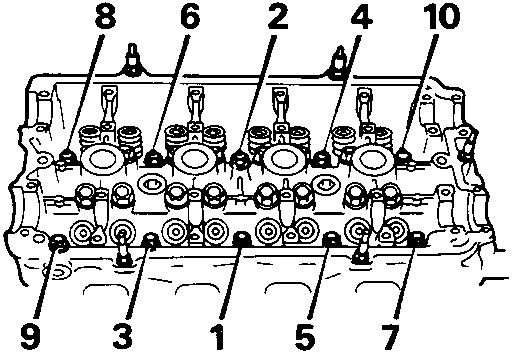
7. Fit each cylinder head bolt and special washer, fit 2 longer bolts at positions 1 and 2. Tighten finger tight only.
8. Working in the order shown, tighten each cylinder head bolt in two stages:
Stage 1 to 30 Nm
Stage 2 to 65 Nm
9. Clean camshafts, holders and bearings in cylinder head.
10. Position tappets in their original positions.
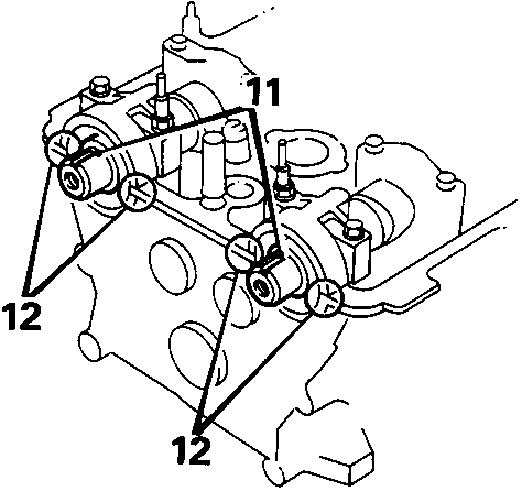
11. Lubricate camshaft journals and lay in position with key – ways uppermost.
12. Apply RTV Sealant to front edge of each No. 1 camshaft bearing holder.
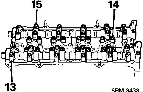
13. Fit camshaft bearing holders in correct order, ensure rocker arms are aligned with camshaft lobes and valves. DO NOT tighten bolts.
14. Slacken tappet adjusting screws.
15. Tighten camshaft bearing holder bolts for each camshaft progressively in sequence to 12 Nm.
Links open Amazon search results in a new tab. As an Amazon Associate I earn from qualifying purchases.
Help keep workshop manuals free
workshop-manuals.com provides free online workshop manuals.
If they helped you fix your car, please consider sharing or
making a small donation to keep the servers running.