
Manual steering rack – 1.4
- Make
- Rover
- Model
- Coupé, Cabriolet & Tourer 200/400 Coupé, Cabriolet & Tourer Workshop Manual
- Section
- Repairs › Manual steering rack – 1.4
SteeringManual steering rack – 1.4
MANUAL STEERING RACK – 1.4
Service Repair No. 57.25.01
Remove
- Raise front of vehicle.
WARNING: Support on safety stands.
- Remove road wheel(s).
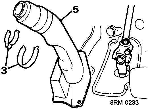
- Remove 2 clips securing column universal joint cover.
- Pull back driver's footwell carpet.
- Remove studs securing column universal joint cover to floor and remove cover.
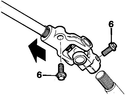
- Remove 2 bolts securing column universal joint and slide joint up column. Disconnect joint from steering rack pinion.
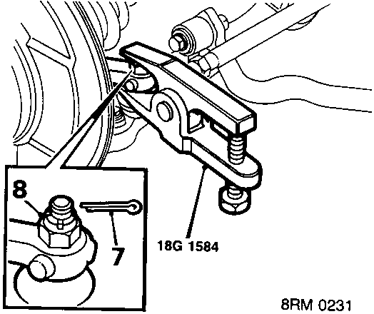
- Remove split pins from track rod end ball joint nuts.
- Remove 2 ball joint nuts.
- Break taper joints using tool 18G 1584.
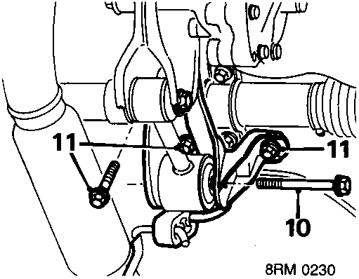
- Slacken bolt, engine steady rod to gearbox bracket, remove bolt release steady rod.
- Remove 3 bolts securing combined engine steady and exhaust mounting bracket to crossmember and remove bracket from exhaust mounting.
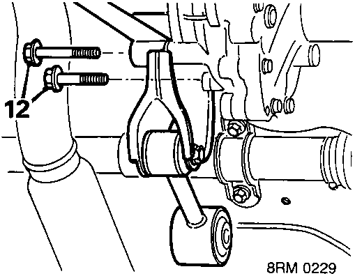
- Remove bolts securing engine steady bracket to transmission and remove bracket.
Parts & tools for this job For Rover Coupé, Cabriolet & Tourer
- TOOLTie rod end toolSearch: tie rod end puller
- TOOLBall joint separatorSearch: ball joint separator
- FLUIDPower steering fluidSearch: Rover power steering fluid
Links open Amazon search results in a new tab. As an Amazon Associate I earn from qualifying purchases.