
Steering lock and ignition starter switch
- Make
- Rover
- Model
- Coupé, Cabriolet & Tourer 200/400 Coupé, Cabriolet & Tourer Workshop Manual
- Section
- Repairs › Steering lock and ignition starter switch
SteeringSteering lock and ignition starter switch · page 1 of 2
STEERING LOCK AND IGNITION STARTER SWITCH
Service Repair No. 57.40.31
Remove
- Remove steering column assembly.
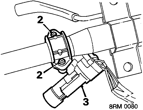
- Drill out shear bolts.
- Remove steering lock.
Refit
- Position steering lock on column.
- Loosely fit 2 shear bolts.
- Rotate column inner until lock plunger engages.
- Tighten 2 shear bolts until heads break off.
- Refit steering column assembly.
MANUAL STEERING RACK ASSEMBLY – OVERHAUL
Service Repair No. 57.10.07 Overhaul
Service Repair No. 57.55.01 Tie – rods 1 – 13
Dismantling
Note: The steering rack assembly should only be dismantled for the fitment of new tie – rods, seals and bushes.
- Remove manual steering rack assembly from vehicle.
- Thoroughly clean rack assembly. Examine for defective housings and bellows to assess the possibility of foreign matter having entered the system.
- Hold pinion housing bracket, with yoke housing upwards, in soft jawed vice.
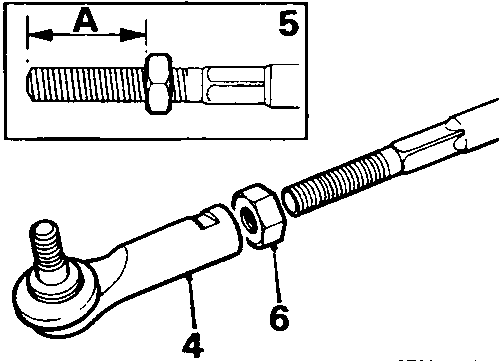
- Hold tie – rod against rotation, slacken locknut and remove outer ball joint from each tie – rod.
- Measure distance 'A' locknuts are screwed onto tie – rods for fitting reference.
- Remove locknuts from tie – rods.
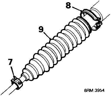
- Remove clip, bellows to tie – rod.
- Cut 'V' into clip at joint, remove clip securing bellows to rack tube.
- Remove bellows from each tie – rod.
- Clean grease from inner ball joints.
Parts & tools for this job For Rover Coupé, Cabriolet & Tourer
- TOOLOBD2 scannerSearch: OBD2 scanner
- TOOLDigital multimeterSearch: automotive digital multimeter
- TOOLBack-probe test leadsSearch: back probe test leads
Links open Amazon search results in a new tab. As an Amazon Associate I earn from qualifying purchases.