
Remove
- Make
- Rover
- Model
- Coupé, Cabriolet & Tourer 200/400 Coupé, Cabriolet & Tourer Workshop Manual
- Section
- Repairs › Remove
SteeringRemove
Service Repair No. 57.25.03
Remove
- Raise front of vehicle.
WARNING: Support on safety stands.
- Remove road wheel(s).
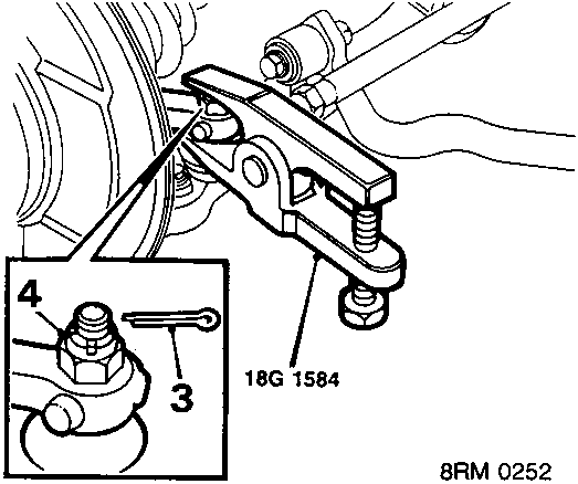
- Remove split pin from track rod end nut.
- Remove track rod end nut.
- Break taper joint using tool 18G 1584.
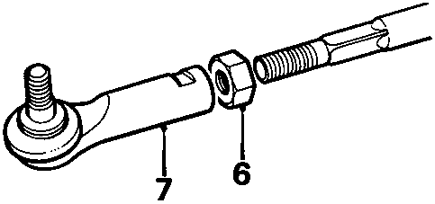
Note: Mark position of track rod end.
- Slacken track rod end lock nut.
- Remove track rod end.
- Remove lock nut.
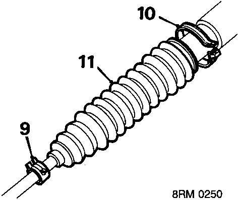
- Remove outer gaiter clip.
- Cut and discard inner gaiter clip.
- Release gaiter from rack and remove gaiter.
Refit
- Apply grease supplied to inner joint and inside of gaiter.
- Fit gaiter to rack.
- Fit and tighten inner gaiter clip.
- Fit outer gaiter clip to track rod.
- Fit lock nut and track rod end.
- Connect track rod end to steering arm.
- Fit and tighten nut to 44 Nm.
- Fit split pin.
- Tighten track rod end lock nut to 55 Nm.
- Fit road wheel and tighten nuts to 100 Nm.
- Remove stand(s) and lower vehicle.
- Check and adjust front wheel alignment, see Adjustments.
Note: Outer gaiter clip should only be fitted after adjustment to wheel alignment has been completed.
POWER STEERING PUMP – 1.4
Service Repair No. 57.20.14
Remove
- Raise R.H. front of vehicle.
WARNING: Support on safety stands.
- Remove power steering pump drive belt, see MAINTENANCE.
- Place drain tin to catch fluid loss.
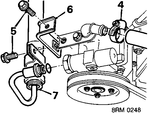
- Slacken inlet hose clip and disconnect hose.
- Remove bolt securing outlet hose to clip.
- Remove outlet hose clip.
- Disconnect outlet hose from pump and plug hoses.
Parts & tools for this job For Rover Coupé, Cabriolet & Tourer
- TOOLTie rod end toolSearch: tie rod end puller
- TOOLBall joint separatorSearch: ball joint separator
- FLUIDPower steering fluidSearch: Rover power steering fluid
Links open Amazon search results in a new tab. As an Amazon Associate I earn from qualifying purchases.