
Assembly
- Make
- Rover
- Model
- Coupé, Cabriolet & Tourer 200/400 Coupé, Cabriolet & Tourer Workshop Manual
- Section
- Repairs › Assembly
SteeringAssembly · page 1 of 3
- Remove rack assembly.
CAUTION: Ensure rack does not contact bore of rack tube.
- Remove lockstop assembly from rack.
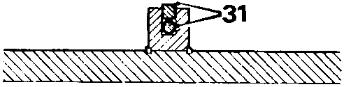
- Remove piston ring and 'O' ring from rack piston.
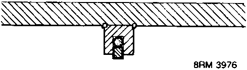
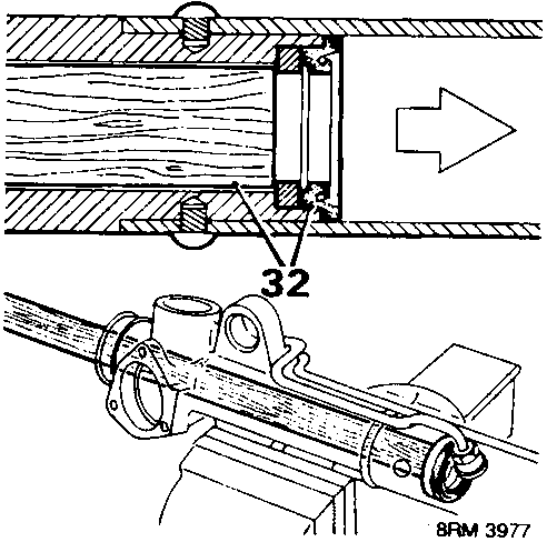
- Using a 25 mm diameter x 600 mm wooden dowel from pinion end, carefully engage support ring and knock seal out of its housing. Keeping dowel clear of bore, push support ring and seal from rack tube.
- Discard all seals, gaskets and components that are to be renewed from service kit.
Assembly
CAUTION: Cleanliness must be observed when assembling, place clean paper over working area.
Use lint free cleaning materials.
Use all components from service kit.
For components requiring lubrication use power steering fluid and only use grease from service kit.
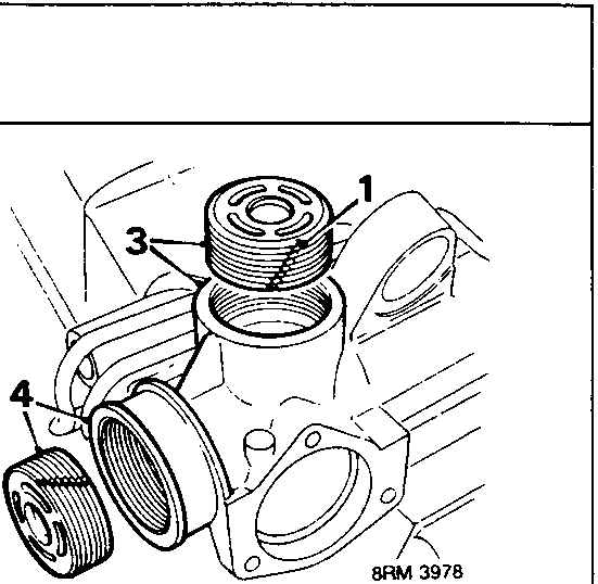
- Service kit contains two yoke covers, on one of these make two saw cuts on opposite sides across threads to use as a thread cleaning device.
- Hold pinion housing bracket in soft jawed vice with yoke housing upwards.
- Using a cutting tool, clean out staking in yoke housing. Using tool 18G 1637/1, screw thread cleaning device into yoke housing to clean sealant from threads.
Remove thread cleaning device and discard. - Clean out 3 valve cover screw threads using a 6 x 1 mm plug tap.
Clean housing and rack tube thoroughly.
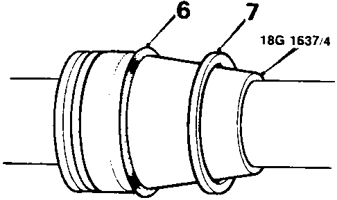
- Locate tool 18G 1637/4 against piston and lubricate.
- Ease 'O' ring into piston groove – DO NOT roll into place.
- Lubricate piston ring, carefully push it onto tool and ease it into place over 'O' ring. Ensure ring is square in groove.
- Remove 18G 1637/4.
- Using fingers, compress piston ring into groove.
Parts & tools for this job For Rover Coupé, Cabriolet & Tourer
- TOOLTie rod end toolSearch: tie rod end puller
- TOOLBall joint separatorSearch: ball joint separator
- FLUIDPower steering fluidSearch: Rover power steering fluid
Links open Amazon search results in a new tab. As an Amazon Associate I earn from qualifying purchases.