
Dismantling (page 2 of 2)
- Make
- Rover
- Model
- Coupé, Cabriolet & Tourer 200/400 Coupé, Cabriolet & Tourer Workshop Manual
- Section
- Repairs
SteeringDismantling · page 2 of 2
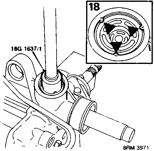
- Release staking securing yoke cover. Clean burrs from thread.
- Using tool 18G 1637/1, unscrew yoke cover from pinion housing.
Note: Cover is also retained with Loctite.
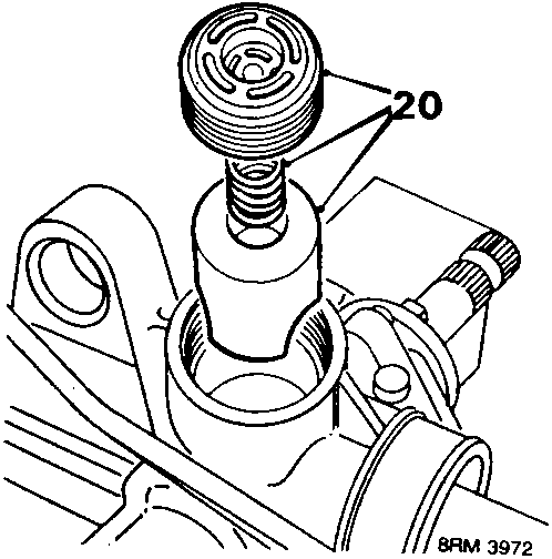
- Remove yoke cover, spring and yoke.
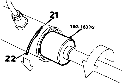
- Push rack to pinion end and remove RTV sealant from slot in rack tube.
- Unwind lockwire by inserting flat end of a small screwdriver in slot and using tool 18G 1637/2 to rotate support bush anti – clockwise.
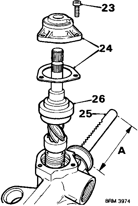
- Apply WD40 around screw heads and using TX30 bit, remove 3 screws securing pinion cover.
CAUTION: Use extreme care to avoid shearing screw heads.
- Remove pinion cover and gasket.
- Position rack so it protrudes 155 mm ‘A’ from pinion housing, this aligns undercut in rack with pinion.
- Holding rack away from pinion, withdraw pinion valve assembly carefully to avoid damage to valve sealing rings and housing seal.
CAUTION: The pinion and control valve are renewed as an assembly, new seals cannot be fitted to the control valve or housing.
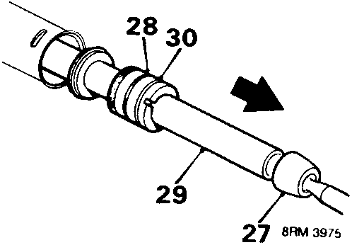
- Temporally fit tie – rod to support bush end of rack.
- Pull rack to support bush end. Extract lockstop assembly from rack tube by giving a sharp pull to tie – rod, if lockstop is tight use a copper mallet on inner face of the inner ball joint.
Parts & tools for this job For Rover Coupé, Cabriolet & Tourer
- TOOLTie rod end toolSearch: tie rod end puller
- TOOLBall joint separatorSearch: ball joint separator
- FLUIDPower steering fluidSearch: Rover power steering fluid
Links open Amazon search results in a new tab. As an Amazon Associate I earn from qualifying purchases.