
Dismantling
- Make
- Rover
- Model
- Coupé, Cabriolet & Tourer 200/400 Coupé, Cabriolet & Tourer Workshop Manual
- Section
- Repairs › Dismantling
SteeringDismantling · page 1 of 2
Service Repair No. 57.10.07 Overhaul
Service Repair No. 57.55.01 Tie – rods 1 to 15
Dismantling
Note: The steering rack assembly should only be dismantled for the fitment of new tie – rods, new seals from the service kit and new pinion valve assembly.
- Remove power steering rack assembly from vehicle.
- Thoroughly clean rack assembly.
Examine for defective housings and bellows to assess the possibility of foreign matter having entered the system. - Hold pinion housing bracket, with yoke housing upwards, in soft jawed vice.
- Remove plugs from hydraulic ports. Position drain tray and pull rack from lock to lock several times to expel fluid.
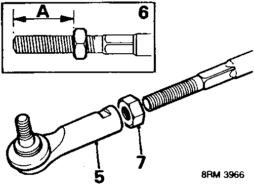
- Hold tie – rod against rotation, slacken locknut and remove outer ball joint from each tie – rod.
- Measure distance 'A' locknuts are screwed onto tie – rods for fitting reference,
- Remove locknuts from tie – rods.
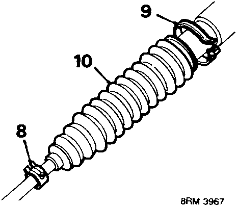
- Remove clip, bellows to tie – rod.
- Cut 'V' into clip at joint, remove clip securing bellows to rack housing.
- Remove bellows from each tie – rod.
- Clean grease from inner ball joints.
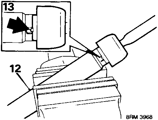
- Extend rack to pinion end and hold flat top of rack teeth in soft jawed vice. Do not overtighten.
CAUTION: Only clamp across the teeth.
- Release inner ball joint stakings from rack slot.
Note: Mark ball joints for refitting reference.
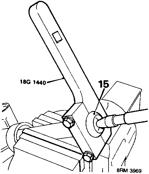
- Fit tool 18G 1440 to inner ball joint.
- Unscrew inner ball joints and remove tie – rods from rack.
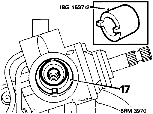
- Hold pinion housing bracket, with yoke housing upwards, in soft jawed vice.
- Push rack to support bush end. Using tool 18G 1637/2, unscrew rack limiter from housing.
Parts & tools for this job For Rover Coupé, Cabriolet & Tourer
- TOOLTie rod end toolSearch: tie rod end puller
- TOOLBall joint separatorSearch: ball joint separator
- FLUIDPower steering fluidSearch: Rover power steering fluid
Links open Amazon search results in a new tab. As an Amazon Associate I earn from qualifying purchases.