
Assembly (page 2 of 2)
- Make
- Rover
- Model
- Coupé, Cabriolet & Tourer 200/400 Coupé, Cabriolet & Tourer Workshop Manual
- Section
- Repairs
SteeringAssembly · page 2 of 2
- Align support bush retainers with rack tube slots and push support bush into rack tube until retainers engage.
- Smear support bush with grease. Fill rack teeth with grease and smear grease on underside of rack along length of teeth. Enter rack into rack tube and align teeth with pinion housing.
- Smear pinion teeth and bearings with grease.
- Enter pinion into housing, align and push bearings into housing.
Gently tap end of pinion with hide mallet to seat bearings. - Using 18G 1637/5, screw pinion cover into place and tighten to 85 Nm.
- Stake pinion housing to cover in 2 places.
- Tape over pinion splines and smear tape with grease.
- Fill inside of pinion seal with grease and press seal fully into pinion housing. Remove tape from splines.
- Extend rack from pinion end and hold flat top of rack teeth in soft jawed vice. Do not overtighten.
- Fit tie – rods to rack and tighten by hand.
Note: If tie – rods are to be reused, fit to opposite end of rack from original position.
- Fit tool 18G 1440/2 to inner ball joints and with torque wrench in line with handle, tighten to 55 Nm (actual fitted torque 80 Nm)
- Stake each ball joint flange into rack slot.
- Hold pinion housing bracket, with yoke housing upwards, in soft jawed vice.
- Centralise rack (equal each side).
- Ensuring yoke housing threads are kept free of grease, fit yoke and spring.
- Screw yoke cover one turn into housing and apply Loctite 542 around the threads.
CAUTION: Adjust yoke cover immediately after applying Loctite before curing commences.
- Ensure rack is centralised and screw yoke cover into place, tighten to 4 Nm using 18G 1637/1.
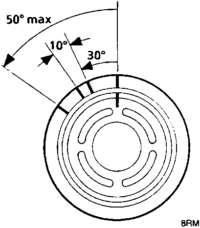
- Using a felt tipped pen, mark a line on yoke cover and housing. Mark a second line on housing 10 mm (30°) anti – clockwise. Turn cover anti – clockwise to align with second mark.
- Pull rack through its full travel side to side. Rack should operate freely over full travel without binding.
- If binding is felt, carefully turn yoke cover a further 3 mm (10°) and recheck full travel. If still tight, repeat above.
CAUTION: Total backing off after tightening must not exceed 16 mm (50°). If rack binds after maximum adjustment, renew assembly.
- Stake housing above yoke cover at 3 new positions.
CAUTION: Ensure staking does not touch cover.
- Smear grease around bellows location on tie – rods.
Apply any remaining grease to rack teeth. - Centralise rack.
- Push bellows onto tie – rods and secure to rack housing with large clips.
Secure bellows to tie – rods with small clips. Check that bellows can rotate on tie – rods. - Screw locknuts equally onto tie – rods to dimension noted on removal or 25 mm. Screw ball joints up to locknuts and lightly tighten locknuts.
Parts & tools for this job For Rover Coupé, Cabriolet & Tourer
- TOOLTie rod end toolSearch: tie rod end puller
- TOOLBall joint separatorSearch: ball joint separator
- FLUIDPower steering fluidSearch: Rover power steering fluid
Links open Amazon search results in a new tab. As an Amazon Associate I earn from qualifying purchases.