
Assembly (page 3 of 3)
- Make
- Rover
- Model
- Coupé, Cabriolet & Tourer 200/400 Coupé, Cabriolet & Tourer Workshop Manual
- Section
- Repairs
SteeringAssembly · page 3 of 3
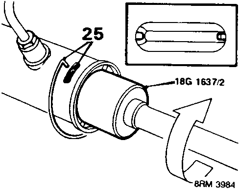
- Locate tang of retaining wire in hole and using tool 18G 1637/2, rotate lock stop clockwise and wind wire into place until hole just shows in slot.
- Seal slot with RTV sealant.
- Push rack fully to support bush end.
- Fit rack limiter and using 18G 1637/2, tighten to 80 Nm.
- Extend rack from pinion end and hold flat of rack teeth in soft jawed vice. Do not overtighten.
- Fit tie – rods to rack and tighten by hand.
Note: If tie – rods are to be reused, fit to opposite end of rack from original position.
- Fit tool 18G 1440/2 to inner ball joints and with torque wrench in line with handle, tighten to 55 Nm (actual fitted torque 80 Nm).
- Stake each ball joint flange into rack slot.
- Hold pinion housing bracket in soft jawed vice with yoke housing upwards.
- Centralise rack (equal each side).
- Ensuring yoke housing threads are kept free of grease, fit yoke and spring.
- Screw yoke cover one turn into housing and apply Loctite 542 around threads.
CAUTION: Adjust yoke cover damper immediately after applying Loctite before curing commences.
- Ensure rack is centralised and screw yoke cover into place, tighten to 4 Nm using 18G 1637/1.
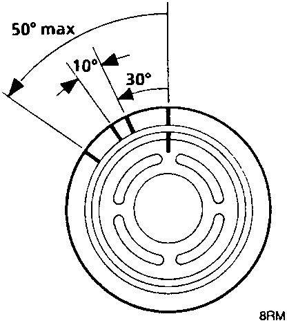
- Using a felt tipped pen, mark a line on yoke cover and housing. Mark a second line on housing 10 mm (30°) anti – clockwise. Turn cover anti – clockwise to align with second mark.
- Pull rack through its full travel side to side. Rack should operate freely over full travel without binding.
- If binding is felt, carefully turn yoke cover a further 3 mm (10°) and recheck full travel. If still tight, repeat above.
CAUTION: Total backing off after tightening must not exceed 16 mm (50°). If rack binds after maximum adjustment, renew assembly.
- Stake housing threads above yoke cover at 3 new positions.
CAUTION: Ensure staking does not contact yoke cover.
- Smear grease to bellows location on tie – rods.
Apply any remaining grease to rack teeth. - Centralise rack.
- Push bellows onto tie – rods and secure to rack housing with large clips.
Secure bellows to tie – rods with small clips.
Check that bellows can rotate on tie – rods. - Screw locknuts equally onto tie – rods to dimension noted on removal or 25 mm. Screw ball joints up to locknuts and lightly tighten locknuts.
Parts & tools for this job For Rover Coupé, Cabriolet & Tourer
- TOOLTie rod end toolSearch: tie rod end puller
- TOOLBall joint separatorSearch: ball joint separator
- FLUIDPower steering fluidSearch: Rover power steering fluid
Links open Amazon search results in a new tab. As an Amazon Associate I earn from qualifying purchases.