
Assembly (page 2 of 3)
- Make
- Rover
- Model
- Coupé, Cabriolet & Tourer 200/400 Coupé, Cabriolet & Tourer Workshop Manual
- Section
- Repairs
SteeringAssembly · page 2 of 3
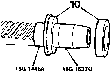
- Fit tool 18G 1446A and 18G 1637/3 onto pinion end of rack. Lubricate seal and holding tools firmly together, slide seal lip first onto 18G 1446A followed by support ring.
- Move assembly over rack and hold 18G 1446A against journal chamfer. Push seal and support ring along journal and against piston.
Remove fitting tools.
CAUTION: Ensure YELLOW anti - extrusion ring is fully seated in back of seal and the spring is seated correctly around the seal lip.
- Fill rack teeth with grease and smear grease on underside of rack along length of teeth. Ensuring rack does not contact bore, enter rack into rack tube and carefully insert seal and piston ring and push rack fully into tube.
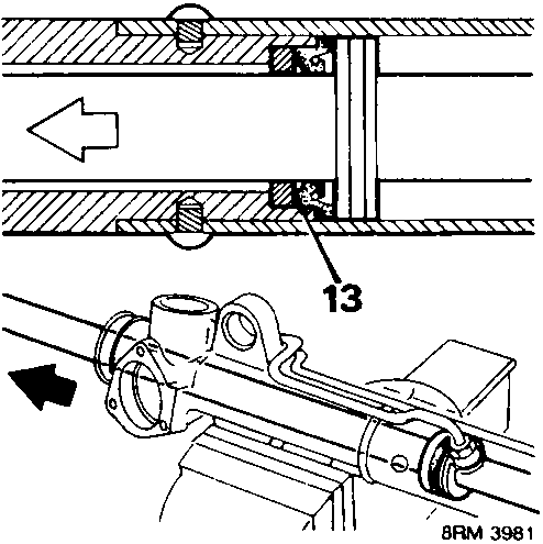
- Screw a tie - rod onto pinion end of rack, pull to engage support ring in housing and then pull firmly to seat seal fully into housing.
Remove tie - rod. - Smear pinion teeth with grease and lubricate valve seals.
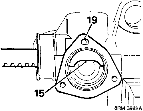
- Align undercut in rack with pinion housing bore.
- Hold rack away from pinion and carefully enter pinion valve assembly into housing avoiding rack contact, align and push bearings into housing.
Using a hide mallet, gently tap end of pinion to seat bearings. Note top bearing stands slightly proud of housing face. - Press pinion seal into cover.
- Tape over pinion splines and smear tape with grease.
Smear grease into pinion bearing and inside cover. - Fit pinion cover gasket, with its elongated slot towards the yoke boss and pinion cover with its timing flange towards the yoke boss. Tighten screws to 10 Nm.
Remove tape from pinion.
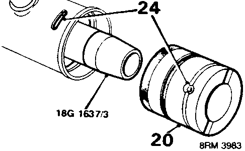
- Check support bush lockstop assembly, ensure seal and 'O' ring are fitted correctly.
- Centralise rack and fit tool 18G 1637/3 onto rack end. Lubricate tool and rack.
- Lubricate 'O' ring, seal and support bush, push lockstop assembly onto rack.
- Remove 18G 1637/3.
- Align hole in lockstop with slot in rack tube and push lockstop into rack tube until hole is centered with slot.
Parts & tools for this job For Rover Coupé, Cabriolet & Tourer
- TOOLTie rod end toolSearch: tie rod end puller
- TOOLBall joint separatorSearch: ball joint separator
- FLUIDPower steering fluidSearch: Rover power steering fluid
Links open Amazon search results in a new tab. As an Amazon Associate I earn from qualifying purchases.